Why SFP Module Pinouts Matter More Than You Think: From Pin Definitions to Hardware Maintenance and Design
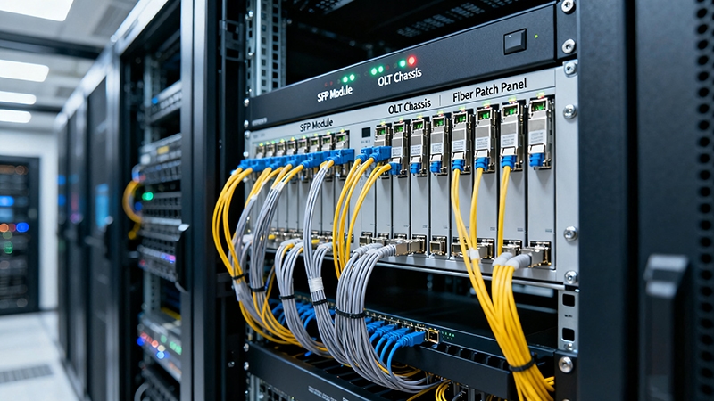
Though small, the pins on SFP modules are essential to network stability. These tiny connections are used to link powerful devices in multi-million-dollar facilities, and their importance goes largely unnoticed. A single miswire or mismatched connector can bring down entire systems, which can cost the company time and money in lost uptime, lost data, or even permanent hardware damage. Not only can questionable electrical specifications affect the stability of operation, but they can also increase potential wear on components or cause electrical components to fail spectacularly.
Understanding SFP module pinouts is more than a technical exercise; it is the basis for reliable network performance. This comprehensive article will detail pin definitions, connector types, and electrical readiness specifications. It will also provide tips to troubleshoot issues in a practical way and lead into evaluating PCB design perspectives and the importance of long-term considerations. Having a high level of understanding of these topics will help keep networks reliable, as well as save network professionals and hardware designers time and money. Understanding these topics will help reduce the potential for costly mistakes and enable design decisions that maximize the longevity of SFP modules.
What is the Complete SFP Module Pinout and What Does Each Pin Do?
Although small in size, the SFP (Small Form-factor Pluggable) module pinout is detailed with a strict and repeatable layout structure. With its standardized pin map and adherence to the Multi-Source Agreement (MSA), pinout standardization ensures both consistency and cross-vendor interoperability. Each pin serves a unique and important function to facilitate seamless data transfer.
Key Pins Overview
- Power Supply Pin (Vcc)
Typically, the Vcc lines will provide 3.3 volts to the module’s internal circuits. For proper operation of laser diodes and the signal-processing circuits, it is critical that this power is stable and well-filtered. Any significant change may lead to transient faults, degraded signal quality, or permanent damage to the module. - Ground Pin (GND)
Ground pins are the reference for electrical circuits. Providing current return and circuit closure, ground also has an important function in grounding noise. Well-grounded circuits will prevent ground loops and help reduce electromagnetic interference (EMI), like an electrical shock protector. - Transmit Data Pins (TX+ and TX−)
The differential pairs are responsible for carrying outgoing data from the host to the network. With a differential signaling approach, the common-mode noise is canceled, providing the best signal performance in the cable assembly. Like noise-canceling headphones that prevent unwanted external noise, the signal quality is held within the cable even in extreme EMI conditions. - Receive Data Pins (RX+ and RX−)
The RX pins receive their signals from the network, implementing the same differential approach as the transmit pairs. When the wired assemblies become packed together inside a dense data center, signal quality very often becomes a function of density; differential signaling is important for effective operation. - Loss of Signal (LOS)
The LOS pin is not a functional pin but serves the purpose of signaling if there is a loss of the incoming signal or if the signal becomes too weak. LOS acts as a status beacon, allowing early detection of fiber damage or signaling interruptions. - Transmit Fault (TX_Fault)
Similar to LOS, TX_Fault is a status pin that indicates that something is wrong internally within the transmission circuitry of the module. TX_Fault may signal malfunctioning drivers, unstable power input, or a failure of the laser itself. Often, these can go unnoticed until the link itself fails, so it’s important to design functions to respond to this fault.
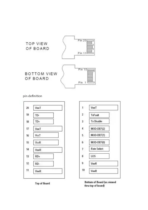
The Layout and Diagram
The SFP module edge connector features an interesting, yet simple configuration with two rows of pins. The top row comfortably lays out the ground and transmit pins for minimum crosstalk, while the bottom row is distinguished with power, RX signal, and several diagnostic pins, or management interface. This arrangement allows for fast, dense, and effective connectivity, as a practical design for a compact module.
Even if the SFP pinout diagram is not exemplary, a good diagram will be labeled to help distinguish functions, reference pins, and power rails. Even when not clear, it should provide some visual aids for engineers to layout the PCB for SFP integration or troubleshoot should there be a problem in the module. Understanding the functionality of the pins and how everything works together also helps take the “black box” out of the SFP integration to better understand the integration process.
How Do Critical Electrical Specs Ensure SFP Module Stability?
The performance of SFP modules primarily depends on strict compliance with electrical specifications. Whether the module is transmitting data cleanly or falls into errors depends on the electrical specifications of voltage, current, and signal levels.
Supply Voltage
Most SFP modules require a 3.3V power supply within a±5% tolerance, which means you should design it to be 3.13V to 3.47V. Providing a voltage supply outside this range will result in error operation or immediate hardware failure. The design must also minimize power ripple because noise on the DC supply can mix into the high-speed signals and cause faulty operation.
Current Draw and Other Protections
Typical current draw should be close to 300 mA, but there are instances of startup inrush or surge currents that are needed when designing the power rail. Power rails should be capable of short bursts of voltage during each transient. Knowing how much current the module draws to perform properly is important for the module and downstream regulators, as excessive current draws can cause regulators to heat up and, in turn, leave components more prone to failure. Circuit protections such as current limiting or thermal shutdown are important to minimize failures that can cascade.
Differential I/O Voltage Levels
The transmit and receive pins carry differential signals to represent the signal with a peak-to-peak voltage swing that is roughly between 400mV and 850mV for I/O signals. The objective is to maintain this amplitude to ensure signals are above the noise floor, while at the same time not being excessive enough to cause electromagnetic radiation or closed-loop reflections.
Think of this like a conversation in a noisy room; the conversation must be loud enough to be heard and comprehended, but not so loud as to disturb others or cause feedback into the microphone or speakers.
Signal Timing and Impedance Matching
In addition to standard voltage levels, specific timing amplitudes and impedance matching of the signal are paramount. The traces must maintain a characteristic impedance generally of 90Ω differential. Trace reflections can be described as the equivalent of not being able to pull a smooth water surface without ripples. This requires controlled traces on the PCB of specific length, width, spacing, and dielectric material to produce the characteristic impedances.
Interoperability
Strict compliance with electrical specifications allows for hot-swapping SFP modules from different vendors without any load, calibration, or setup. If there is a slip in electrical specifications, it often causes links to become unstable, where the devices get stuck resetting, for example, or are unable to complete negotiation.
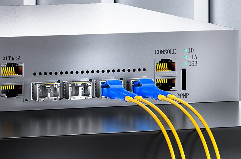
What Are the Main SFP Connector Types and How Do They Impact Compatibility?
The choice of connector largely determines the physical compatibility, signal characteristics, and cable infrastructure of SFP modules.
A Summary of Connector Types
- LC (Lucent Connector)
LC connectors are latch-type, compact, and secure. Therefore, they have become the overwhelming choice in fiber connections that demand higher port density with a compact package that saves space and reduces rack cable clutter. - SC (Subscriber Connector)
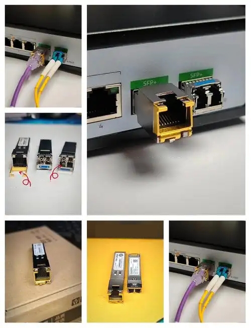
SC connectors are larger in size than the LC but generally operate under the same push-pull latch locking mechanism as the LC connector. They have become very popular in the telecommunication field, providing a cost-effective, rugged connection, but with a larger field footprint for each connector than the LC connector. - RJ45
An RJ45 connector is the standard copper Ethernet module connector. It supports electrical signals and has rugged mechanical contacts. Only copper SFP modules utilize an RJ45. An optical media SFP does not use this connector for fiber optical networks. - MPO/MTP (Multi-Fiber Push-On/Pull-Off Connectors)
The MPO/MTP connector is designed to accommodate multiple fibers in a single connector. These units can accommodate 12 or more fibers in one connector. This connector is an excellent choice for a server farm or data center that has a higher density application. Even though this connector allows for multiple fiber lanes, care must be used to handle and clean the fiber properly.
The Impact on Compatibility and Wiring
Differences in mechanical designs will impact how the SFP module will fit into a device’s ports. The LC connector can be accommodated in compact SFP cages, while SC connectors will require more space to access its ports. Another example is the RJ45 connector, where the cabling infrastructure must be copper. Lastly, the MPO/MTP connector will affect the complexity of routing fiber cables and the topology of the network.
While connector choice is mostly influenced by the installation environment and the potential for future growth in a network, compatibility is a must when ensuring proper electrical functioning and the correct pinout of the connections.
How to Use SFP Pin Signals to Quickly Diagnose Hardware Issues?
Diagnostic Pins in SFP Modules
Diagnostic pins built into SFP modules provide quick and helpful visual indicators of link health that can help troubleshooters in rapidly diagnosing faults.
Diagnostic Signals in Detail
- TX_Fault
The TX_Fault signal indicates a high output when the transmitter section is having a problem, including failure of the laser, over-temperature, or unstable power. - RX_LOS (Loss of Signal)
A RX_LOS indicator appears when an incoming optical or electrical signal falls below the manufacturer’s justified threshold, suggesting there may be a break in the optical fiber or defective connector.
The Flow of Troubleshooting
- Consider the Signs
Symptoms like disconnections, slow throughput, and device alerts are great indicators of hardware issues. - Verify TX_Fault
If the TX_Fault is lit, you can usually confirm a problem exists with the transmission hardware and not with an external cable. - Verify RX_LOS
If the RX_LOS has illuminated, it indicates an issue with the incoming signals, either from fiber damage or contaminated connectors. - Physical Check
Look for obvious signs on the connectors, cables, and modules inserted on the motherboard; many issues can be recognized by bad connections, bent pins, or dirt. - Electrical Measurement
Using basic electrical meters, voltage and signal quality can be measured on the TX and RX pins to help validate electrical concerns. - Replace or Reseat Module
Sometimes module receivers can experience mechanical contact issues; during troubleshooting, simply removing and then reseating or replacing the module can resolve signal path problems.
Efficiencies
The ability to use a pin-level diagnostic signal resolves much fault location time and expedites signal path fault detection; this can help reduce downtime and mean a faster repair process for a technician, as it gives immediate direction to the faulty part of the signal path instead of a trial-and-error process.
Why Did a Single Pin Misconnection Nearly Break a Network?
A simple mix-up of two pins almost caused a complete failure of the network, reminding us how critical it is to make sure the pins are wired correctly.
Event Summary
Initially, inconsistent link drops were attributed to bad SFP modules. Even after replacing the modules, the problems continued, which caused frustration.
Pin-Level Discovery
An inspection found a swapped wire connection for the Vcc (power) pin and the TX_Fault (transmit fault) pin, creating an unstable voltage supply, which generated periodic transmitter errors.
Why This Is Important
It is not an acceptable practice to transmit power and fault signals across swapped pins; this method may lead to electrical damage and system resets. It could be compared to mixing up the fuel with the brake in a vehicle; that will cause a mess, instead of working like a vehicle smoothly.
Path to Resolution
After re-verifying the pin definitions and fixing the wiring to be correct, the power was restored to a safe level. Immediately, the link started to work normally again, avoiding a possible major outage.
What to Take Away for Your Practice
- Verifying the accuracy of pin wiring should not be compromised.
- Errors across single pins will cause problems across networks.
- Having a review process will catch bothersome unproductive time and prevent costly outages.
How Do Different Brands’ SFP Pinouts and Interfaces Compare?
In multi-vendor environments, understanding brand-specific pin/parameter nuances prevents compatibility pitfalls.
| Feature | Cisco SFP | Juniper SFP | Brocade SFP |
| Power Voltage (Vcc) | 3.3 V (±5%) | 3.3 V (±10%) | 3.3 V (±5%) |
| TX/RX Differential | 400–850 mV | 350–900 mV | 400–850 mV |
| Diagnostic Pins | LOS, TX_Fault, TX_Disable | LOS, TX_Fault, TX_Disable | LOS, TX_Fault, TX_Disable |
| Connector Type | LC | LC or SC | LC |
| Pin Arrangement | MSA-compliant layout | Shielding variations | Slight pin mapping variations |
Compatibility Points
Juniper has a wider voltage tolerance for powering compared to Cisco and Brocade modules, which have stricter voltage tolerance, and their pin shielding varies. Differences in the area of signal amplitude must be accounted for to ensure signal integrity while hot swapping modules across brands.
Extended Compatibility
In addition to differences in the pinout, the brands vary in the mapping of the EEPROM addresses, internal thermal management, and the state of the modules during hot plug. If used incorrectly in a mixed brand environment, these differences can lead to errors.
Buyer Recommendations
- Always confirm your exact pin and electrical specifications prior to installation.
- Use authorized modules for the given brand whenever possible.
Finally, ensure you maintain clear inventories and labeling when working with different brands.
How to Design a PCB That Follows SFP Pinout for Reliable Signal Integrity?
PCB design is an important factor that influences signal quality traveling through SFPs.
Pin Routing
Route all traces precisely according to the MSA pinout specification. This is important, as misrouting causes signal interference, loss, and crosstalk, which may cause traffic accidents due to mixed-up routes.
Power and Ground Plane
Having solid ground planes right under the signal layers is effective in shunting electromagnetic interference away from sensitive signals. Power planes need to provide stable voltage and low noise and ripple to sensitive analog devices.
Route Differential Pairs
TX and RX differential signal pairs require:
- Tightly coupled (close trace spacing)
- Length match to less than 5 mils difference
- Controlled impedance (about 90Ω differential impedance)
All of this routing is necessary for the trace to maintain its nulling capabilities for noise rejection and phase matching.
EMI Considerations
Twisting the differential pairs and proximity of ground vias to through-hole connectors and appropriate trace spacing mitigates the EMI interference impact. Being compliant with connector-specific mechanical standards (such as LC’s latch structure) will minimize any mechanical/electrical instability.
Important Signal Integrity
Never sharp bend or stub traces. Controlled impedance can prevent ringing and what could be reflections from impairing the quality of the signal that leads to bit errors. Also, place decoupling capacitors in proximity to power pins to help flatten the voltage supplies.
More Technical Detail
Using software tools like HFSS or ADS can help simulate high frequency and optimize the PCB design with parasitic capacitance and inductance. Designing for EMI and going through EMC testing will provide opportunities to validate design choices under real-world scenarios. Design a plan for thermal management to remove heat from the laser diode and electronics. Although it is an SFP module, if it is in a dense enclosure, the module design will extend the laser diode and electronics’ life.
What Are Best Practices to Maintain SFP Modules and Avoid Pin and Power Damage?
Implementing maintenance will help prolong SFP module longevity while enabling continued network uptime.
Safe Handling Practices
When inserting or removing modules, do so directly along the axis of the connector. Avoid applying lateral force when inserting and removing the modules, as this lateral force may bend the pins and cause damage. Be sure to unlatch the module from its latched position prior to removal to avoid contact damage to the connectors.
Static Electricity Management
Make sure that all technicians are grounded using a wrist strap or grounded mat. Consider the SFP modules as sensitive electronic devices that can detect static discharge (ESD), which can be invisible and very harmful to the SFP itself.
Cleaning Strategy
Clean fiber optics as needed using lint-free optical wipes or another kit designed specifically for this purpose. Fiber optics can endure a variety of substances. Dirt that is microscopic in scale can still cause EML signal attenuation or reflection. This can be compared to shooting a picture through a dirty camera lens; the dirt will diminish and impact the quality of the image.
Electrical Verification Plan
At particular intervals, verify that you can pull power off rails, check signal amplitude, and check diagnostic pin readouts to ensure they are being read in the initial state. Identify deviations from specifications before hardware failure occurs.
Power Compliance
In many cases, SFP modules will specify voltage and current. Make sure voltage and current are operating within acceptable ranges. Overheating and accelerated wear can occur if either voltage or current vary from the operating specification. In general, use power supplies that operate as close to the actual specification as possible, and verify load behavior.
Summary List
- Apply all forms of care and gentle handling
- Utilize stringent ESD protocols
- Perform regular fiber cleaning
- Monitor electrical and compliance systematically
- Confirm the module’s electrical conformity if power compliance is suspected.
Conclusion
By mastering SFP pinouts, you are unlocking the secret to stable and reliable network hardware. When you understand what each pin does and all of the important details of the SFP’s interface, you can make the right connections, avoid misuse and damage, and optimize troubleshooting. Mastering the SFP pinout will help you maintain efficient data flow and avoid unexpected failures.
When you plug in the SFP’s connectors properly, you’re going to follow electrical standards and specifications to protect sensitive components and enhance the service life of the optical module. When you discover signals related to diagnostic pins, you’ll hasten the resolution of networking issues and, most importantly, get your network back up and running as quickly as possible.
When networking professionals regard the SFP pinout as one of their critical skill sets, it gives network teams complete authority and reliability over hardware disputes. Similar to learning how to play a musical instrument, if a professional is calibrated to the use and function of every pin, connector, and SFP signal, they will no doubt be able to maintain and execute each SFP in their rack without an issue. Moreover, developing these skills will usher in disconcerting network stability skills, quick to operate, and successful service life.
Reference Sources
- Juniper Networks
RJ-45 Port, SFP Port, SFP+ Port, QSFP+ Port, and QSFP28 Port Connector Pinout Information
Detailed tables and explanations of connector pinouts for SFP and related transceiver ports, covering pin functions and layout. - FiberPlex
SFP-BHDVXC User Manual
User manual covering SFP transceiver identification, diagnostic monitoring, and electrical pad layout for integration and troubleshooting. - SNIA (Storage Networking Industry Association)
Small Form-Factor Pluggable (SFP) Transceiver MultiSource Agreement (MSA)
Official MSA documentation with detailed pin definitions, mechanical, and electrical specifications of SFP transceivers for interoperable network design. - Cisco
Cisco SFP Modules for Gigabit Ethernet Applications Data Sheet
Technical specifications and features of Cisco SFP modules used in enterprise network applications.