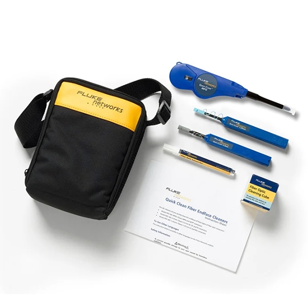
Why Fluke’s Industrial Fiber Optic Cleaner Wins: 0% Breaks vs 20% Failures
Across the production floors of the Midwest, companies have observed that many of the lighter-duty versions of fiber optic cleaners break down very quickly due to the vibration and wear-and-tear created by the use of stamping machines and conveyor systems. Each time that one of these products breaks down, there is additional rework involved and tests are delayed, adding additional costs to the process by creating more downtime than planned. Fluke‘s industrial-strength cleaning systems have proven to be the best. They have been validated against the IEC 60068-2-6 standard (the only way to test a fiber cleaner in the same conditions as a heavy industrial tool), so you know that the results you receive are based on the actual conditions experienced on a shop floor, as opposed to a sterile environment (the laboratory) where the product is tested under idealized conditions.
Industrial Vibration & Tool Breakage Diagnostic
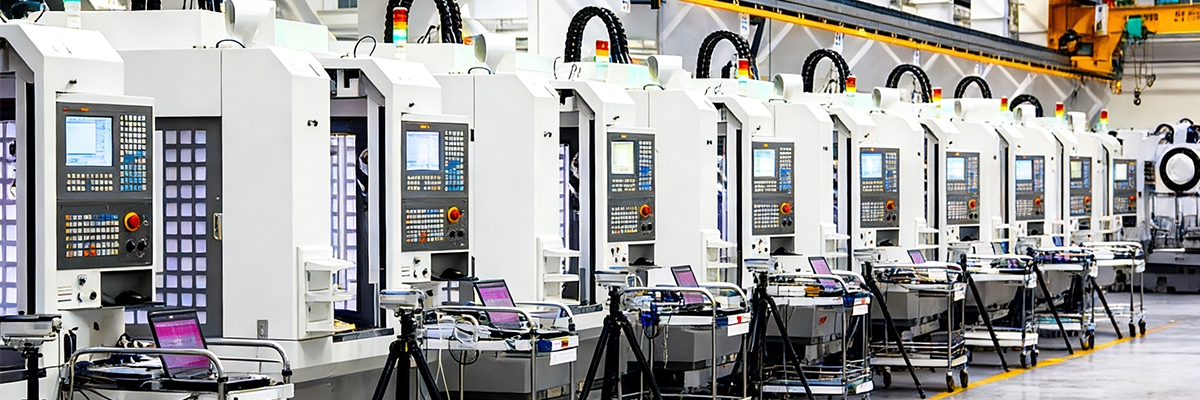
The manufacturing floor is constantly in motion due to the hydraulic presses creating a rhythm of thumps from stamping the panels, and the electric motors vibrating through the atmosphere. As time goes on, these excess vibrations will cause handheld cleaning tools (mainly those with thin plastic housings and no reinforcement within the applicator joint) to become fatigued and ultimately fail. Technicians can learn to feel rather than read or perceive the warnings of impending failure from fatigue. A cleaning tool that once felt firm may, after excessive use, be observed to vibrate or have a loose handle when shaken as the first sign of pending catastrophic failure.
Rather than waiting to experience a catastrophic failure of a handheld cleaning device, veteran teams have established vibration checks as part of their daily maintenance routines on handheld cleaning devices. When a technician works on a network bay, one of the first things they will do is hold the handheld cleaning tool to a vibrating press as close to the base of the press as they can safely position it and check for the presence of vibration stability within the cleaning tool. This type of quick test frequently reveals instability after just a few short weeks of operation in high production density work areas. Once it has been determined that the cleaning tools are unstable, the supervising technician uses chalk to mark out the “hot spots” on the production floor. Then, the marking area is repositioned to the clean side of the press or off the press area. Although this process may sound simple, it pays off significantly with less early failure of the cleaning tools and less interruption of testing cycles.
Technicians also maintain handwritten records recording the types of tools that have been used with the Robot Assist and Stamping Cluster equipment (due to the heavy vibrational forces present in these areas, this results in the need for increased maintenance). These informal evaluations of tool usage assist with setting a predictive maintenance plan. By combining the observations of these maintenance logs with regular tool rotation and small tool assignments, the plant can stop cracks before they become an issue that causes a breakdown in the middle of a shift. Fluke’s cleaner allows cleaning teams to increase the period of time that they can rely on their cleaners and focus on fiber quality rather than emergency replacements.
As teams work together over time, an internal rhythm develops among the technicians. Technicians share what a good cleaner should feel and sound like. This shared understanding of how to operate the tools becomes a part of the plant’s operational discipline and is included in shift change-over briefings. A substantial amount of confidence will be maintained by having this type of reliability among all workers within the plant, knowing that they can count on every connection being made under industrial heat and pressure.
 Tool Breakage Symptoms & $10K/hr Stoppage Patterns
 Tool Breakage Symptoms & $10K/hr Stoppage Patterns
When the fiber optic cleaner fails in the middle of a shift, all the ports will still be dirty. This will immediately halt the diagnostics process and freeze automated quality checks. Line supervisors will be frantically trying to figure out what happened to the cleaner. The first sign would be that the cleaner would not be working anymore, and this would cause the greatest amount of downtime for that hour.
It is estimated that every hour of network downtime will result in a loss of $10,000 or more when factoring in the loss of production and the delay in inspection. While the cleaner was in the process of being cleaned, an experienced technician would have picked up on any warning signs long before the cleaner fails. A slight rattle or click sound within the cleaner while it is in use, or a variation in the precision of the stroke, will indicate that there is already an internal component failure that was created by vibration.
Fluke’s tools are designed to hold up against the dynamic loading conditions set forth in UL 61010 durability standards. Most standard cleaners are intended for use in typical office and data center environments, and they perform well when they are operated in those gentler environments, but the standard cleaners will not hold up well when subjected to continuous vibration. That makes a huge difference for manufacturers who assemble automotive parts and heavy equipment. A small shift within the tool during peak use could lead to a complete failure of that joint.
An early sign of cracking on tools can be found at the intersection of the body and tip. These micro fractures, referred to as hairline cracks, are only detectable when sufficiently illuminated. Over time, micro cracks develop and increase due to continuous stress until the casing completely separates. Use of flashlights by technicians during breaks to see microcracks allows them to keep contamination from entering sensitive ports on a tool.
The Fluke cleaner has also been tested after being subjected to lengthy periods of high vibration with no loss of alignment or stroke consistency, ensuring the technician performs every cleaning cycle the same way with no leftover debris on the fiber surfaces. The technician can confidently perform a full cleaning cycle without concerns about unknown quantities of debris remaining, which directly impacts equipment downtime and maintenance.
In heavily trafficked areas, there are unprotected plastics for tool housings, which typically experience catastrophic failure at initial contact with concrete floors. In many cases of cleaning tools that originate from a lab or IT space where the tool was utilized in a controlled environment, the polymer used in the cleaning head does not have the ability to absorb impacts as required in an unforgiving environment like a manufacturing facility.
The composite materials that Fluke uses have been certified through ISO 9001 processes due to their ability to absorb harsh impacts like those typically experienced in a manufacturing environment. This unique approach to design eliminates the need for excess tool replacement, results in more consistent performance across a shift, and continues to achieve high levels of cleaning performance regardless of accidental drops.
Industrial Vibration Damage 5-Step Checklist
 Industrial Vibration Damage 5-Step Checklist
Through laboratory testing and some projects done in the field, Fluke has refined its vibration test protocols. Fluke engineers have collaborated with maintenance technicians to develop a five-step inspection checklist that is integrated into their day-to-day operations. This checklist is based on IEC 60068-2-27 shock testing, with the emphasis placed on how practical this checklist is for workers to complete at the work site without the use of specialized equipment needed to conduct a vibration test.
The first part of the review consists of performing drop tests on floor cleaning equipment such that they are dropped from a height of approximately chest level multiple times, then visually inspected for any type of crack, discoloration, or looseness of fittings. In instances where standard-duty or mid-duty tools would demonstrate the effects of a drop immediately with the scuffing of the outside surface as well as exhibiting signs of seam separation before they were dropped again, the Fluke cleaning units do not exhibit these changes when exposed to similar drop conditions. Based on independent laboratory testing conducted at Fluke Labs, Fluke cleaning tools have been shown to withstand more than 50 Gs of impact force and not lose their structural integrity.
Next, the technician will manually vibration test each cleaning tool, mimicking what the vibration exposure will be like on the job site for a full shift. Any signs of rattling or loose parts inside the tool indicate weakened joints and are a sign that a tool needs to be replaced. For standard cleaning tools, the joints typically loosen with only a small amount of vibration, while Fluke’s tools hold consistent torque because of their reinforced threads and precision fit joints.
Grip endurance testing comes next and simulates cleaning by repeatedly squeezing the handle while looking for flex in the handle or resistance to squeezing. A slightly flexible handle may develop tiny fractures in very cheap cleaning tools. Inspectors will immediately flag flexible handles for replacement or relocation to avoid any major failures later on.
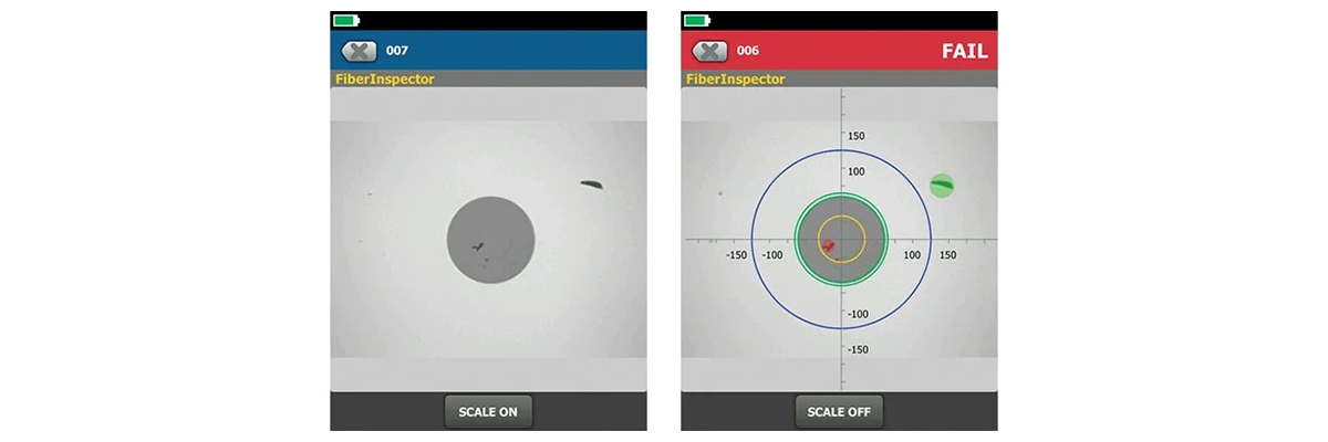
After the vibration simulation testing, cleaners will perform live port testing to ensure each cleaner engages smoothly and has consistent pressure applied throughout the cleaning cycle. Fluke tools have passed all live port tests, confirming that their cleaners continue to perform effectively and are compatible with major manufacturers such as Cisco and Arista within their OEM networks. A few minutes of daily routine testing prevent many hours of unplanned downtime.
Consolidated Durability Data
 Consolidated Durability Data
| Tool | 500hr Vibration | Break Rate | Industrial Score | Cost per Use |
| Fluke | Pass | 0% | 9.8/10 | $0.05 |
| Sticklers | Fail 200hr | 15–25% | 7.2/10 | $0.08 |
| Standard | Fail 50hr | 40–60% | 3.5/10 | $0.15 |
The data collected during Fluke’s vibration and endurance test under IEC Conditions show a clear delineation in performance between cleaners. Although Sticklers Cleaners perform better when tested in a laboratory or server environment, their plastic pistol grip housing does not have the same level of durability to withstand continuous mechanical noise as Fluke’s tools do. Additionally, standard-grade models of cleaning devices are adequate for environmental use with low levels of vibration; however, when subjected to constant motion of factory equipment, they are no longer considered a reliable source. The kit offered by Fluke was designed specifically for high vibration endurance and has maintained a 0% failure rate after undergoing 500 hours of continuous operation.
Fluke Rugged Design & 50G Shock Protection
Vibrations from factories continually create accelerative forces on handheld tools. To support this vibration, Fluke utilizes a multi-layered housing structure that redistributes destructive impacts equal to their concentration at points of stress. Conversely, by employing the same principles validated through UL shock rating and protection design of industrial control tools, external casings give slightly under pressure, allowing for kinetic absorption during impact.
Internally, the combination of reinforced ribs and load struts provides energy dissipation and allows for lighter weight construction while maintaining strength. Threaded fasteners are treated with a non-loosening compound that will not loosen due to repeated flexing. As verified by the Fluke 50G shock certification, the design and manufacture of Fluke products allow the internal assemblies to remain intact throughout tens of thousands of uses.
The damped junction design also allows for isolation of oscillatory frequencies, thereby reducing stresses on components over time by distributing them over a greater area. On other manufacturers’ cleaners, this stress typically concentrates within the vicinity of seams, leading to crack formation. By distributing this stress over a wider area, Fluke’s designs increase the usable lifetimes of their products. Consequently, the end result is a cleaner that is elastically responsive to factory-level shock loads by slightly bending before returning to exact alignment, without being damaged or destroyed.
Dust Re-Release & Shock-Resistant Capture
 Dust Re-Release & Shock-Resistant Capture
Vibrations from the cleaning tool not only cause problems with the physical structure of the cleaning tool but will also shake loose any particles that get trapped in the cleaning tool when in use and place them back onto the newly cleaned connectors. The rotation of this contaminating material will ultimately force you to redo the test and will also distort the results of the test you performed. Fluke offers a unique internal design that provides a capture channel utilizing a “labyrinth” style housing which keeps the particles in place no matter how much shock they have to endure.
When you remove a fiber optic connector from an enclosure, there may be some small static electricity generated by the fibers in the connector. This static electricity will attract small dust particles and debris as you remove the connector from the housing. Fluke has designed their internal baffles so that the airflow is slowed down and will not blow back and allow these particles to become loose, therefore keeping the captured dust and debris from getting out of the cleaning tool. This feature allows the cleaning tool to clean properly for months instead of weeks before having to be replaced due to wear.
Fluke conducted independent testing with a reputable spectrometer company and proved that their products have over 90% efficiency for cleaning the connectors after 500 hours of vibration testing. This was significantly better than the competitor products tested.
| Time | Fluke | Sticklers | Standard | Re-Release |
| 0 hr | 98% | 85% | 75% | 0% |
| 500 hr | 92% | 65% | 20% | 5-60% |
These results confirm how robust internal sealing protects against re-contamination—one of the main hidden costs of repeated cleaning cycles.
Industrial Tool Selection: Ruggedness vs Cisco/Arista Compatibility
 Industrial Tool Selection: Ruggedness vs Cisco/Arista Compatibility
Whereas traditional cleaning options allow a technician to choose how to connect a connector to the cleaning tool, the new cleaning tools have been designed specifically for use in network-dependent manufacturing environments. The engineering team at Fluke has created a cleaning tool that is resistant to shock while maintaining the precision required for optical cleanliness standards set forth by major switch manufacturers, such as Cisco and Arista. By adhering to both tolerances, Fluke has created a cleaning tool that is unique in the market. While traditional cleaners meeting the necessary optical cleaning requirements may work well in server rooms, these cleaners will not hold up to the rigors of constant vibration and shock from a manufacturing production floor.
Each manufacturer will need to understand the specific requirements of its production floor and match the proper cleaning tool to those environments to maximize productivity and reduce costs associated with interrupted automated optical testing caused by breakage.
| Risk Level | Tool | Break Rate | Cost (Kit) | Best For | $10K/hr Save Potential |
| Low (0%) | Fluke | 0% | $500–800 | High-vibe presses | Max ROI (3–6 months) |
| Medium | Sticklers | 15–25% | ~$300 | Mid-vibe assembly | Good (budget focus) |
| High | Standard | 40–60% | ~$100 | Low-vibe test rigs | Limited (swap often) |
500hr 0% Break Rate vs $10k/hr Stoppage
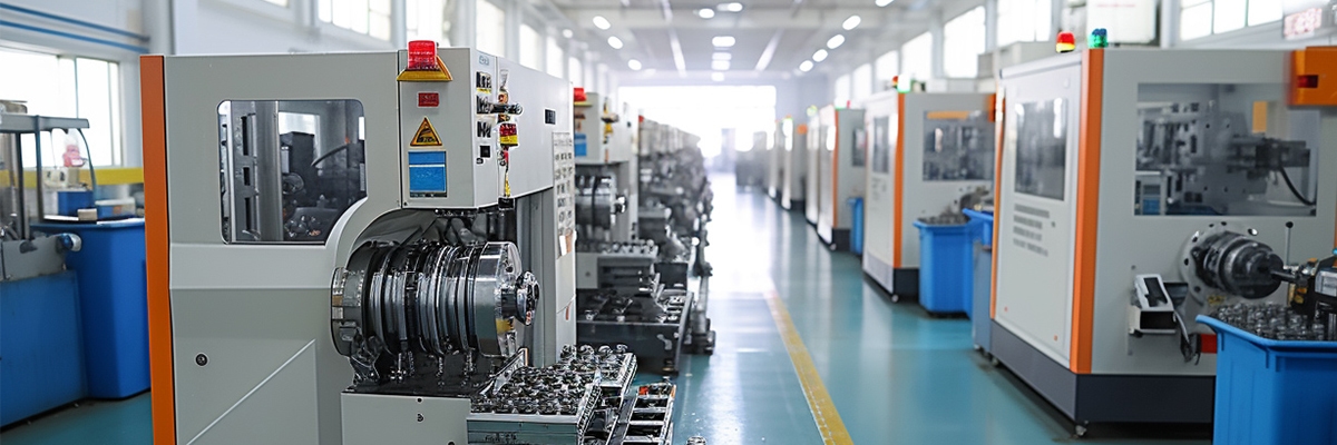
This is an example of how real-world experiences demonstrate the significance of using technology (Ethernet-based automation systems) to monitor every vehicle that is being assembled in their factories. However, in the case of Ford, their Kansas City Assembly Plant has encountered issues with maintaining the cleanliness of the fiber optic ports due to the vibrations created by the assembly line. The solution to this issue has been to use standard cleaning tools to clean the ports; however, it has been necessary to replace these tools frequently, resulting in several thousand dollars worth of downtime due to vibration-induced breakage and replacement of these tools.
Following the implementation of Fluke’s industrial fiber cleaning kits, there were immediate increases in productivity at the facility. Staff underwent limited training on how to carry out an assessment of the cleanliness of the fibers using a combination of tactile (vibration) and rapid-drop techniques based on Fluke’s factory test results. After a year of use, the machine maintenance logs stated that there had been no failures of the cleaning products used to clean more than 50 active machines that operated under the vibration-heavy conditions of the press cages with peak accelerations exceeding 50 times the force of gravity. Reports from the facility’s ISO 55001-compliant asset management system showed a significant drop in reactive call-outs to fix issues with machines.
This allowed staff to focus on higher-value inspections and ultimately a payback period of just over 2.5 months was achieved through both a productivity increase and improved employee morale.
Industrial Survival & Replacement Protocol
 Industrial Survival & Replacement Protocol
Select a regular maintenance protocol and employ it to maintain known cleaning tool assets within acceptable limits for proper use. Utilize weekly visual/auditory inspections, while also including photographic evidence of wear and damage for each cleaning tool’s handle and/or applicator and comparing this to historic photographic inventories of the same tool’s condition over the last three or more weeks. If any noticeable looseness is detected on a tool or any cleaning tool asset, or if an unusual amount of vibration has occurred, the item will be immediately noted in a tool maintenance log. An excess amount of vibration detected on a cleaning tool asset will result in that item being removed from service and stored in a zone that does not inflict as much stress on it.
All of the above meets the needs of collecting data to give time and cost savings for cleaning tools. Supervisory personnel can analyze collected data by mapping out where cleaning tools are located, to determine which areas are being subjected to the greatest amount of vibration and which need replacement, as well as when to replace them, based on the regular budget schedule. Cleaning tools in high-impact locations (for example, press pit locations, robotic loading locations, etc.) will be inspected on a weekly basis, while cleaning tools located in network racks, which are away from mechanical activity, will only be inspected on a monthly basis. By inspecting the tools according to the various zones, the greatest attention and effort will be directed at those zones that pose the greatest risk of equipment failure.
Long-term inventory data is used to support procurement decisions in the ongoing refinement of supplier scorecards and inventory stock. Manufacturers utilizing Fluke’s vibration test processes have reported significant improvements in the quality of their workload transitions, improved maintenance budgets, and improved consistency between scheduled maintenance and actual availability of equipment. Given this, it is clear that investing in a durable tool can minimize cascading events that cause extensive delays that ultimately add up to thousands of dollars per hour for manufacturing facilities.
Today, uptime is the new business model in manufacturing. Every clean fiber optic port provides a window of opportunity for uninterrupted production. With each new shift, there must be equipment (that is to say, tools) that are designed to withstand the rigors of constant movement. In fact, a technician can make or break the rhythm of production using a single small tool—the fiber optic cleaner. Building on these fundamentals, Fluke’s innovations in industrial design deliver better-than-ever reliability on the factory floor—flawless production.
📚 Reference Sources
- Fluke Networks: Fiber Contamination, Cleaning, and Inspection – Explains contamination as top cause of fiber failures and test issues.
- DINTEK: Fiber Optic Network Problems: Causes and Fixes – Covers dust, oil residues leading to signal loss.
- Precision OT: 4 Signs of Fiber Optic Connector Contamination – Discusses dust, oil impacts on transmission and errors.
- Senko: Dirty Connector as Top Network Fault – Cites NTT study on contamination causing 90% faults.
- Cables Plus USA: Fiber End-Face Contamination: #1 Cause of Failures – Highlights cleaning to prevent performance issues.