Patch Cord vs Ethernet Cable: Same or Different?
Based on historical data, nearly 85% of intermittent connection problems within a network stem directly from a cable-related failure at the “physical” layer and are among the first items to check during Physical Layer (Layer 1) troubleshooting into an intermittent connection problem. When there is any form of packet loss on 10G networks or video conferencing applications experience buffering during heavy periods of use, IT personnel often adjust switch settings or firewall rules prior to checking the basic cabling within the network. According to TIA-568 standards, the main source of these packet loss and video lag problems occurs primarily from incorrectly swapping out patch cords and solid-core horizontal cables. While both types of cables utilize the same type of RJ-45 connectors, it is easy for someone to mistakenly pull the wrong type of cable from a spare cable drawer.
Patch cords should only be used for short, flexible connections such as connecting equipment from a rack to a patch panel or running cables to a workstation where the length of the cable is typically only a few feet. Solid-core horizontal cables are typically used for longer, permanent cable runs that run through walls and across floors. While the two types of cables look the same, it is important to remember that using one type of cable at a distance greater than its rated length will result in significant differences in the quality and performance of both types of cables. The installation of both types of cables is regulated by TIA-568 standards.
 Is a Patch Cord the Same as Ethernet Cable?
 Is a Patch Cord the Same as Ethernet Cable?
At the Desk: The Moment of Doubt
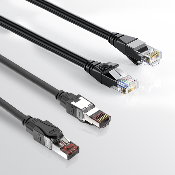
As you sort through piles of tangled wire while sitting at your desk every day, you will occasionally reach a patch cord that clicks neatly into place in the switch port. Patch cords and Ethernet cables are very similar when viewed from a distance, which is why it is so easy to grab one of these cables when you are looking for something close by. The actual type of conductor used within each of these cables dictates how good the performance is for a data signal over long distances when using either type of cable. Jacket markings provide a great way to determine what type of patch cord you have selected. Look for print on the jacket that contains designations such as “Cat6 Stranded” and ANSI/TIA-568, which indicates that the patch cord is designed to withstand repeated flexing while being used in racks or at patch panels.
Stranded patch cords consist of multiple fine copper strands twisted together for flexibility. In contrast, solid Ethernet cables feature a single solid conductor, providing superior electrical performance over distance but lack flexibility. To determine the quality of the conductors inside the cable, strip a small section of the conductor on one end of the cable. TIA-568 standards limit the total length of patch cords in a 100-meter channel to 10 meters.
Material, Length, and Label in Action
If you find that the stripped copper conductors are all the same color throughout their length, the conductors are made from pure copper and will provide low-resistance connections for mounting in switch racks. If, however, you see silver-colored aluminum wire under the copper covering, you are holding a CCA (copper-clad aluminum) cable, which will have 55-60% more resistance than pure copper and will overheat quickly when subjected to heavy loads and does not support Power over Ethernet (PoE) consistently. Ethernet cables marked “Solid” are specifically engineered to span large distances, such as from one end of a room to the other, using a single thick wire that is capable of transmitting signal over a longer distance but cannot be subjected to sharp bends or curls. Stranded patch cords are designed to work in a flexible environment, such as behind a desk, but distortion increases much quicker once you begin to extend the range of the stranded patch cord beyond its design.
Stranded cables allow for flexibility for short links under 1 meter, such as switch-to-router connections, without incident. Industrial-grade solid-core cables support long distribution runs with a balance between length, twisting, and copper quality—however, alloy-based cables can cause 10 Gigabit Ethernet signals to degrade.
Fast Visual Checklist
 Fast Visual Checklist
In order to avoid hours of troubleshooting after connecting to multiple switches, it’s a good idea to spend a minute doing some simple checks using these guidelines:
- Read the Cat rating and stranded/solid information printed on the side of the jacket; the type of conductor used will determine which application is best for that type of cable.
- Perform a scrape test on a small end section; pure copper will show its true color, while CCA will show signs of having a silver-clad, which indicates that the cable is likely to fail.
- Match the cables to the distances required; stranded cables can be used for up to 10 meters, while solid cables are for fixed runs, typically longer than 10 meters.
- Confirm the connectors you are using; LC/SC are used for fiber, while RJ45 are used for copper.
Pure copper stranded conductors (24/26 AWG) patch cords may work well under the correct conditions; however, when tested using real-world equipment, they will reveal their 10G limitations. This technical guide now shows how to properly read cable labels, verify the quality of the conductors, and perform simple tests on the cable to identify if one cable matches another, all without needing to invest in expensive cables/equipment. In the case of using a Cat6A cable, the maximum allowable length for a Cat6A channel is 100 meters, and that Cat6A channel can contain up to 10 meters of stranded patch cord on each end of the channel, provided the stranded patch cords are manufactured with either 26 AWG or 24 AWG pure copper conductor material. Standardized testing ensures maximum network uptime.
Why Copper Ethernet Patch Fails Over 7 Meters in 10G
 Why Copper Ethernet Patch Fails Over 7 Meters in 10G
A 10G Setup Meets Its Limit
When design firms extend their Network Attached Storage (NAS) or SAN environments over more than two meters using copper patch cables, they often do not consider what will happen to their system in the morning, especially when they move their cables slightly farther than they typically do. The most common source of these disruptions is increased resistance due to the use of multiple small individual strands of copper wire, known as stranded wire, which results in an increased amount of insertion loss and return loss distortion, causing signal-to-noise ratio (SNR) degradation, which triggers TCP-layer retransmissions. Short runs of copper cable, less than three meters, can dissipate any additional heat created by longer-length runs without any issues. However, long runs, greater than three meters, of copper cable, especially with poorly made or crimped connectors or CCA (copper clad aluminum) conductors, create noise that interferes with the ability to send packets. This results in multiple attempts to resend, which 1G networks mask but 10G networks will expose when the system is under heavy traffic.
Survey results have shown that between 70–85% of budget stranded patch cords do not meet TIA (Telecommunications Industry Association) performance specifications, resulting in VoIP (Voice over Internet Protocol) jitter or delays in database query requests. Below are a few of the key metrics obtained from Fluke-style testing over various Cat5e runs that indicate a caution zone:
| Length | Return Loss (dB) | 10G Retransmit % | Ping Jitter (ms) | Network Status | Recommendation |
| 1m | -35 to -30 | <0.1 | <1 steady | Green | Rack ideal, zero loss |
| 3m | -32 to -28 | 0.1-0.5 | 1-2 | Green | Good, reliable |
| 7m | -28 to -22 | 0.5-2 | 2-5 | Yellow | Caution if poor quality, VoIP clips |
| 10m | -25 to -18 | 2-5 | 5-10 | Red | Fail if poor crimp/CCA, queries lag |
| Shielded | +5-10dB gain | Halves | 50% cut | Yellow-Green | Partial save, noise help |
| CCA | -20 to -15 | 10-20 | 10-20 | Fail Red | Total failure |
| 1G | N/A | <1 | <1 | Green | Fallback, basic use |
This performance drop primarily affects Unshielded (UTP) or low-quality CCA cables. Certified Cat6A S/FTP patch cords can maintain integrity up to 10 meters.
Reading the Numbers Behind the Slowdown
 Reading the Numbers Behind the Slowdown
According to the Fluke tester patterns for cables, the performance of cables appears to be good in the green zone (good) under 3 meters, yellow (warning) between 3–5 meters, and red (poor) from 7–10 meters, with VoIP jitter and losses exceeding 30% when they have bad crimps or CCAs, not just due to the distance alone. Stranded cables create an unevenly distributed pattern of electricity through the wires. This results in different amounts of resistance being created, which causes the integrity of the digital data to become blurred. An email sent through a stranded patch cord will look fine, but if you try to use a stranded patch cord to send a live collaboration session, the session will be impacted significantly. At 10Gig capability of up to 500 megahertz of frequency, if the wire is loosely twisted, any looseness will increase the amount of near-end crosstalk (NEXT) caused by an interfering signal on one pair of wires near the connector of another pair of wires, thus causing video stutters to become worse.
Why Shielding and Tricks Don’t Save It
Foil shielding may prevent most, if not all, external interference to the internal signals, but foil shielding does nothing to reduce internal signal losses at the point of termination or from the cumulative resistance of the conductor and cable run for each meter. Almost all manufacturers of Cat6A stranded patch cords have the capability of reaching 10 meters within a 100-meter channel to TIA-568 specifications, provided that the patch cord meets TIA-568 specifications completely. There are countless ways in which businesses lose money due to the extra milliseconds that occur because of this issue. For example, warehouse inventories often increase their time to sync by two or more times. A medical facility’s diagnostics, scans, etc., often take two or more times longer to load when they use stranded patch cords to connect their systems. Patch cord loops found in server racks are typically the first items to be located and examined to determine if there is an underlying issue.
Fiber Optic Patch Cord Wins Where Copper Ethernet Can’t
 Fiber Optic Patch Cord Wins Where Copper Ethernet Can’t
The Tsuen Wan Turnaround
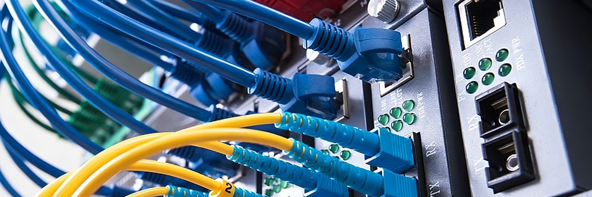
After months of intermittent connectivity due to faulty copper cables in otherwise functional and busy office buildings, teams switched to using fiber patch cords and, within a matter of hours, experienced a return to a fully functional 100G throughput. Fiber optic systems do not transport electricity as part of the transmission. They are therefore not affected by electrical interference, allowing for the establishment of stable links.
Why Fiber Moves Where Copper Chokes
The glass core of a fiber optic patch cord transmits light rather than electricity. Hence, no electromagnetic crosstalk exists between two fiber optic cables located close to one another inside the rack. Therefore, racks that contain copper cables must allow for greater spacing to prevent interference, resulting in increased rack airflow and greater ease of maintenance. Fiber optic cables transmit light and are completely immune to Electromagnetic Interference (EMI) and Radio Frequency Interference (RFI). Laboratory tests have shown, however, that copper losses are typically 10 meters, while fibers have been shown to maintain a clear signal over distances up to 300 meters. Replacing traditional telecom trunk lines using fiber patch cords can save as much as 50% of the time and effort associated with the initial deployment of the service and up to 80% of the number of trouble tickets.
The Real Estate of the Rack
When space is valuable, minimizing the amount of space used for rack and equipment configuration and documentation is critical. In terms of air circulation and weight, the use of fiber allows for better air circulation between equipment and fewer overall rack-weight restrictions. A single technician can quickly and easily reroute a panel within the equipment and completely reconfigure the layout of the network room.
Why Duplex Counts More Than Cost in Fiber Optic Patch Cord
 Why Duplex Counts More Than Cost in Fiber Optic Patch Cord
Simplex fiber requires two separate strands for bidirectional communication, whereas Duplex LC simplifies connectivity in 10G–100G SFP+ environments. In addition, the OM4 standard for 50/125μm multimode cables creates a stable path for signals, even during peak traffic times.
Slot Compatibility: The Hidden Gatekeeper
RJ45 ports are limited to copper data only. SFP ports must contain an optical module to accept data from any source; so if you plug copper into the SFP port, it will remain dark (it won’t transmit any data). Copper connectivity in SFP ports requires 10GBASE-T SFP+ transceivers. If you use the same model of transceiver with a duplex OM4 fiber, you can significantly increase your throughput overnight based on deployment statistics. According to industry experts, matching compatibility greatly outweighs the initial cost of building a legacy brand. The following table illustrates how copper Ethernet and fiber optic patch cords differ:
| Metric | Copper Ethernet Patch | Fiber Optic Patch Cord |
| Connector | RJ45 booted | LC duplex + SFP |
| 10G Dist | 100m channel/10m patch | 300m full |
| EMI Resist | Medium w/shield | Fully immune |
| Core Verify | Pure Cu scrape test | 50/125 μm OM4 label |
| Duplex | Built-in | Required |
| TCO/Gbps | Higher labor/heat | Lower maintenance |
| Fail Sign | Rising jitter | Link stays dark |
| AWG/PoE | 24AWG=90W, 28AWG limited | N/A power delivery |
Counting the Real Cost and Return
Copper may seem less expensive at first, but as you start to need more space and to be able to cool the space, those higher costs will eventually be counteracted by the value of fiber. As well as being able to use smaller trays, fiber provides for easier repair and is less demanding on power than copper, which translates into much higher profits over time. Companies utilizing duplex OM4 have reported twice the number of questions answered, backups completed hours ahead of schedule, and have experienced zero unplanned downtime, realizing their return on investment in the first quarter. Matching equipment to your needs is critical; the testing steps that follow will help you find the equipment that provides the best performance.
How to Test and Upgrade: Is a Patch Cord the Same as Ethernet Cable
 How to Test and Upgrade: Is a Patch Cord the Same as Ethernet Cable
Step 1: Measure Before You Replace
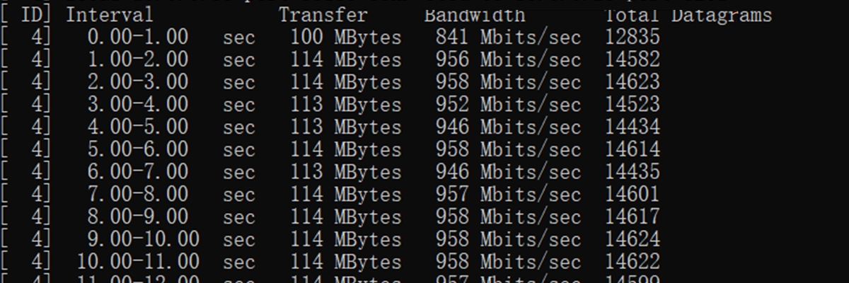
Without question, you need to measure everything before making any hardware changes or attempting any fixes. The first type of measurement that must be taken is an iPerf3 Server-to-Client measurement to assess the jitter and packet loss on each of the connections between the two devices. You must create a document of all test results taken from the iPerf3 testing. Any time the amount of packet loss exceeds 1%, this indicates that there are possible wiring issues with the cabling used. Call stutters, or calls dropping in and out, should cause you to closely inspect the connectors on both ends of the connection for any tangling or poor connection of the cable. Cat6A cables should be terminated with shielded RJ45 connectors. The entire channel, including the patch panel, must be grounded to dissipate noise. QSFP/SFP transceivers are required for use with duplex OM4 fiber cables.
Step 2: Match Cable and Equipment
Because SFP-labeled ports only accept fiber, only use fiber patch cables. As soon as you have the correct transceivers and fiber patch cables, the connection should be checked for connectivity. As a rule, do not use copper Cat6A cables for any lengths longer than 10 meters in 10G channel budgets, and in noisy environments, fiber should be used. One of the main reasons there were so many trouble tickets taken to factories was because of the change in zone segregation from backbone fiber and patch. Keep detailed logs of which fiber patch cables and transceivers were ordered and received to ensure the proper equipment is being used.
Step 3: Execute and Recheck
After making any changes to patch cords or transceivers, you should re-run the iPerf3 Server-to-Client test to ensure the send and receive rates are still matched and have low jitter. You should also document the baseline results of the iPerf3 test prior to scaling. Always perform fiber end-face cleaning thoroughly; dirt on a connector interface destroys the signal faster than any mechanical wear or tear. A consistent reading overnight will indicate that the signal has returned to its baseline range. Using the systematic process of testing, matching, and verifying will continue to produce as reliable and predictable device performance as possible.
AWG Gauge Guide for PoE Reliability
 AWG Gauge Guide for PoE Reliability
Power is delivered via AWG markings; for example, 24 AWG wire supports 90W PoE for both access points and cameras because of its low resistance. Conversely, thinner 28 AWG wire limits the current below 1.4A, causing excessive heat build-up in cable bundles, violating IEEE 802.3bt safety margins. 24 AWG to 26 AWG should be verified by looking at the jacket print, as they are known to reduce the occurrence of intermittent faults by at least 80% according to several Fluke surveys. Professionally bundled 28 AWG wire used with 90W PoE Type 4 will heat up quickly and cause either the wire jacket to soften or signal loss as a result of the 24 cables in that bundle. The thicker gauges prevent this from happening and keep everything within the safety limits. Use the following jacket code decoder for assistance:
| Code | Description | Practical Impact |
| CM | General use | General Purpose (Non-Plenum) |
| CMR | Riser-rated | Riser (OFNR/CMR) |
| CMP | Plenum-rated | Plenum (OFNP/CMP) |
| 24AWG | Thickest gauge | Max PoE 90W no drop/heat |
| 26AWG | Medium gauge | Balanced flex/power |
| 28AWG | Thinnest gauge | Short runs; bundle heat risk |
| UTP | Unshielded | Clean environments |
| FTP | Foil-shielded | Moderate EMI |
| STP | Braided-shielded | Heavy interference |
Shielding Types for Noisy Environments
While UTP provides sufficient capability for offices with low ambient noise, it is limited by excessive electromagnetic interference (EMI) generated by electric motors and will not perform properly in the presence of these devices. Therefore, use F/UTP foil for normal EMI environments, while U/FTP braided shields will provide the most protection when operating in extreme EMI environments. By selecting the right product based on the physical conditions of your site, you can reduce your instance of unexplained slowdowns by approximately 60%. For FTP/STP cables, it is necessary to connect both ends of the drain wire to the ground through the shielded patch panel and the chassis of the equipment where the cables are connected in the data center to separately provide full equipotential bonding at all high-frequency EMI points. Failing to connect both ends may allow for potential voltage on the wire, which could lead to incomplete shielding and therefore failure to protect from EMI.
Twist Density and Crosstalk Prevention
To reduce crosstalk between pairs, it is required to maintain uniform density of tightly twisted wires both along the length of the cable and at the point where the wires are terminated. Loose-twist designs have been known to permit external interference that will cause significant degradation to 10G signal performance.
Permanent Link vs Channel Testing
Permanent Link Testing covers all runs of cabling in the wall; the Channel Test adds the use of patch cords to provide a total distance of 100 meters. Patch cords have historically caused most failures. As such, it is essential to conduct comprehensive testing of complete channels (including all crimps) to ensure accurate results. Managers can maintain maximum performance levels for many years by routinely establishing iPerf3 baseline tests. These baselines provide information on any degradation of a channel since its initial testing. If an increase in the jitter value indicates an increase in the frequency of patch changes, then they should be replaced in advance of potential outages.
Stranded vs Solid Physical Structure
Physical builds compared:
| Aspect | Stranded Patch Cord | Solid Ethernet Cable |
| Wires | 7-50 thin strands | Single solid core |
| Diameter | Smaller per pair | Larger rigid |
| Bend Radius | Tight 4x diameter | Wide 8x diameter |
| Use Case | Movable desk/rack | Fixed wall/floor |
| Attenuation | 20-50% higher/NEXT risk | Optimized long-haul |
| Cost | Higher flexibility premium | Bulk economical |
Material Safety Check: Spotting CCA Fakes
 Material Safety Check: Spotting CCA Fakes
By combining and verifying information, it is clear that CCA constantly shows up as the culprit. Since CCA scraped ends (where the copper cladding is) reveal the most resistance (55-60% worse), that the CCA overheats on both load testing and Power over Ethernet, and that CCA will fail TIA testing. While solid copper remains visually solid in color and functions properly under load conditions without issues, it is advisable to discard any CCA immediately when encountered. Due to industry standards regarding reliability, factory-stranded patch cables exceed the performance of site-crimped solid wire patch cords, which lead to increased 10-Gigabit contact failures due to their inflexible structure.
In conclusion, matching cables properly will prevent network issues. Pure solid copper Ethernet cable should always be used for long-walled runs; stranded patch cords, made from pure stranded copper conductors, should only be used for short jumps under 5 meters (15′) via rack or desk. Any cables identified as CCA or with a silver scrape should be discarded immediately. The first step should be to check the jacket and conductors for verification of the product, followed by iPerf3 tests performed prior to and after any swaps used to identify jitter or anomalies via the testing process. By TIA standards, the total length of the patch must not exceed 10 meters within the channel. However, the quality of the cables will significantly increase insertion loss on lengths greater than 7 meters. Power over Ethernet expects 24 AWG wire within the bundle to avoid excessive heat drops. Shielded cables must be designed with drain wires connected to the ground panel at each data center location to provide optimal EMI protection at high speeds. Both factory and office/factory test sites cutting tickets in half/2x speeds provide daily motivation to continue following the 30-second checklist: Read, Scrape, Match, Test.
Reference Sources
- ANSI/TIA-568 – Wikipedia – Core standard for structured cabling, defining patch cord lengths up to 10m in 100m channels and horizontal cabling specs.
- CCA Vs. Solid Copper Ethernet Cables – Details CCA risks like 55% higher resistance, PoE failure, fire hazards, and TIA non-compliance.
- Patch Cable vs Ethernet Cable Guide – Compares flexibility, length, stranded vs solid use cases, and key differences in network setups.
- Solid vs. Stranded Ethernet Cable – Covers performance over distance, attenuation, flexibility, and ideal applications for each type.
- Maximum Ethernet Cable Length – Charts Cat5e to Cat8 limits for 10Gbps (e.g., 37-55m Cat6), relevant to 7m+ copper failures.