Patch Cable vs. Crossover Cable: What’s the Difference in Ethernet Networks?
The concept of Ethernet networking is a core principle of modern communication; therefore, it’s extremely important to select the appropriate cable type to guarantee efficient and dependable connections. Patch cables and crossover cables are types of Ethernet cables. Although they may seem structurally identical externally, it is what is inside each of these cables and their intended use that tremendously differ. Whenever professionals and Ethernet networking enthusiasts learn the differences between cables, they can set up, troubleshoot and enhance networks more appropriately.
Introduction
Ethernet networking uses several types of cables to connect devices on the same local area network (LAN). Patch cables (also called straight through cables) and crossover cables are two common cable types. A patch cable has the same wiring configuration at both ends of the cable and is generally used to connect different types of devices to each other (like a PC to a switch or a switch to a modem).
A crossover cable essentially swaps the transmit and receive pairs on each end, which enables two identical devices to be connected and communicate with each other (like two computers or two switches).
Understanding the differences between patch cable and crossover cable is important for connectivity issues and ensuring a successful network. For example, if you were to connect two computers directly with a patch cable, without the crossover wiring, that cable could cause a signal collision and prevent proper communication between the computers. A crossover cable resolves this issue by crossing the transmit and receive pairs.
T568A and T568B are wiring standards that describe how the wires inside the CAT5e, CAT6 and CAT6a cables are arranged. In a patch cable, both ends of the cable wire the same standard, T568A or T568B. In a crossover cable, one end will have T568A and the other end will have T568B; the wires will cross the transmit and receive pairs.
In this article, we will provide a detailed comparison of patch cables and crossover cables, practical examples of when to use each type of cable, basic wiring diagrams and answer some frequently asked questions to help you choose the best cable for your needs.
Understanding Wiring Standards: T568A vs T568B
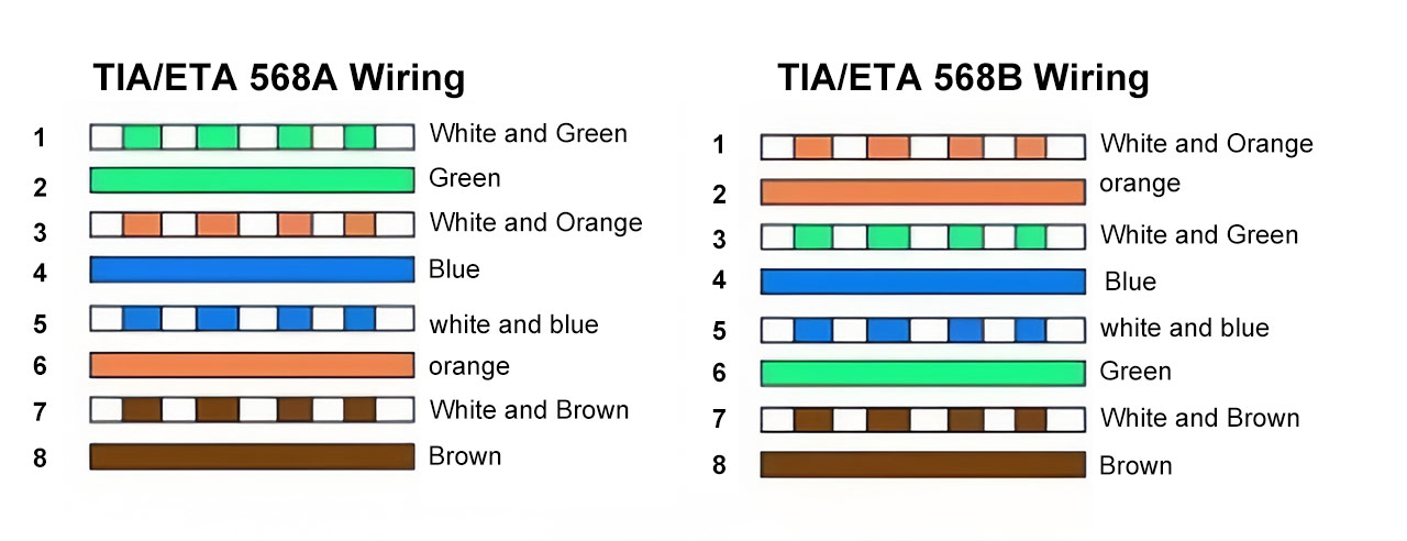
Ethernet cables follow two primary standards: T568A and T568B. These standards denote the order of color of the eight wires that are twisted into four pairs inside of an RJ45 connector. The main difference between T568A and T568B is the order of the green and orange twisted pairs.
- T568A – White/Green, Green, White/Orange, Blue, White/Blue, Orange, White/Brown, Brown
- T568B – White/Orange, Orange, White/Green, Blue, White/Blue, Green, White/Brown, Brown
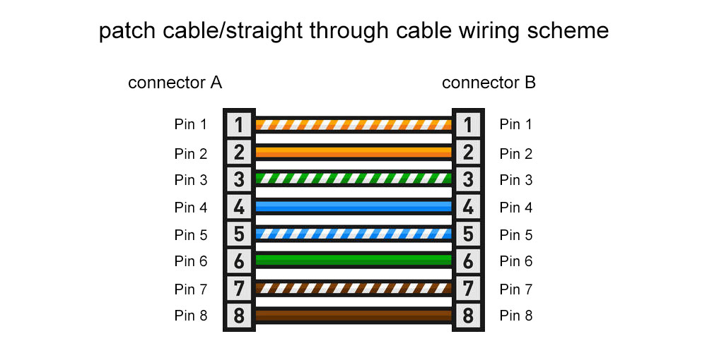
A patch cable uses the same wiring standard on each end of the cable (if T568A is used on one end, T568A must be used on the other end, same with T568B) which is referred to as a straight-through cable. In this configuration, each pin will correspond to the same pin on the other end and allows two devices to communicate with each other.
A crossover cable uses T568A wiring on one end and T568B wiring on the other end; this effectively reverses the transmit and receive pairs. The crossover will allow two of the same device to communicate with each other directly without needing another device such as a switch or router.
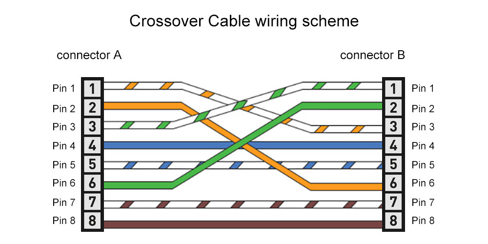
Below is a wiring diagram of patch and crossover cables:
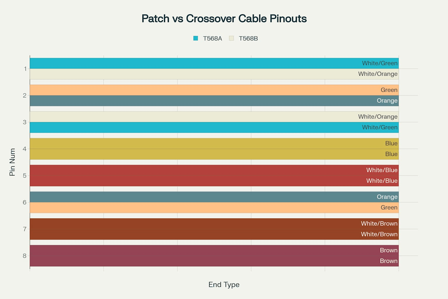
Wiring diagrams for both patch cable and crossover cable which show the pin numbers and wire colors of the patch cable (both ends) at T568A and T568B standards:
This chart shows the patch cable keeps the wiring the same on both ends whereas the crossover cable switches pins 1 with 3 and 2 with 6 allowing for device-to-device communication without any interface.
What Is a Patch Cable?
Also referred to as straight-through cables, patch cables make up the most common type of Ethernet cable. Patch cables have the same wire configuration on both ends, either T568A or T568B. This means that they are designed to connect different devices utilizing the same wire configuration on both ends.
Typical Scenarios for Use
Patch cables can be used to connect:
- PC to switch
- Router to modem
- Switch to patch panel
- Device-to-network infrastructure
Since patch cables have an identical wire configuration, they ensure communication between devices by keeping the transmit pins of one aligned with the receive pins of the other.
Why Patch Cables Are Conspicuous
The prefix “conspicuous” simply means noticeable and noteworthy, which patch cables seem to be in a home or office network. Patch cables are designed to connect devices and are compatible with almost everything you will run into. Patch cables exist in a variety of categories such as Cat5e, Cat6, and Cat6a, which can provide up to 1Gbps and 10Gbps or more. This can depend on the manufacturer and the network equipment being used in conjunction with the patch cables.
Patch cables exist in different colors that can be used toward cable management and identification in a structured cabling system. The common colors of patch cables include blue, gray, and white.
Other Uses
Patch cables can be used outside of a computer networking scenario. One example is a patch cable connecting a guitar to an amp. Again, these cables are designed for completely different purposes but the general use of patch cable will refer to any short cable used to connect devices and relays to a patch panel, for the purpose of connecting devices in a signal chain.
What Is a Crossover Cable?
A crossover cable has different wiring than a patch cable. One end uses T568A wiring and the other end uses T568B wiring, basically swapping the transmit (TX) and receive (RX) pairs. This wiring is specifically designed to connect two devices that are similar in function, for example, two computers or two switches. Using a crossover cable allows two similar devices to connect without using an intermediary device such as a switch or router.
Typical Applications
Crossover cables are used to connect:
- Two computers for file transfers or multiplayer gaming
- Two switches to expand a network
- Two routers to bridge networks
- Two hubs (in older network technologies)
Why Crossover Cables Are Necessary
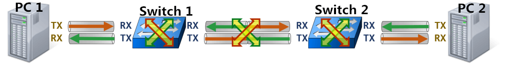
If two similar devices are connected with a patch cable, both devices will transmit on the same pins, which will result in signal collisions and communication failure. A crossover cable crosses the transmit and receive pairs, meaning that TX pin 1 on one device is connected to RX pin 1 on the other device.
The Effect of Auto MDI-X
Many modern devices support Auto MDI-X. This feature will automatically detect the type of cable connected and automatically switch the device’s TX and RX pins based on the cable type. Auto MDI-X has made crossover cables almost obsolete, as a patch cable can be used regardless of whether or not they are required. However, crossover cables will still be necessary in legacy networks, in industrial applications, or in situations where Auto MDI-X is not supported.
Wiring Information
The crossover cable crosses pins 1 and 3, 2 and 6. This crossover cable design will ensure the signal will flow correctly and eliminate collisions.
Patch Cable vs Crossover Cable: Key Differences and When to Use Each
Knowing the differences between patch cables and crossover cables can help you set up a network correctly or when you have a need to troubleshoot a network.
| Feature | Patch Cable (Straight-Through) | Crossover Cable |
| Wiring | Same standard on both ends (T568A or T568B) | T568A on one end, T568B on the other |
| Use Case | Connects different devices (PC to switch) | Connects similar devices (PC to PC) |
| Signal Flow | Direct, matching TX to RX | Crossed, TX to RX swapped |
| Device Compatibility | PC, switch, router, modem | PC to PC, switch to switch, router to router |
| Modern Auto MDI-X Support | Often sufficient | Less needed with Auto MDI-X |
Examples in a Practical World
- PC to Switch: When connecting device types, you will use a patch cable.
- PC to PC: When communicating directly between devices without a switch, a crossover cable is used.
- Switch to Switch: When connecting switch devices, a crossover cable is utilized unless the devices support Auto MDI-X.
- Modern Devices: Most modern devices now auto-negotiate the need for a crossover or patch cable, so using a patch cable works in most situations.
As a whole, the level of performance achieved by using the correct type of cable is much greater than carrying out any troubleshooting of cables used with network devices.
How to Identify and Make Your Own Crossover and Patch Cables
Identifying Cable Types
The first step is to inspect the wire colors on each RJ45 connector termination you are trying to determine if the cable is a patch or crossover.
- Patch cables will have the same color sequence from the same point.
- Crossover cables will exchange the orange and green pairs (pins 1 & 3 and 2 & 6).
Making A Crossover Cable
To make a crossover cable, follow these simple steps:
- Strip the jacket and untwist the wires.
- On one end, line up the wires according to T568A and the other end according to T568B.
- Trim the wires to make them even.
- Insert the wires into the RJ45 connector and crimp.
- Test the cable, optionally, with a cable tester.
Tools needed:
- Cable stripper
- RJ45 crimper
- RJ45 connectors
- Cable tester (optional)
Tips:
- Always double-check the order of the wires before crimping.
- Always make sure the wires are fully seated in the connector.
- Always test the cables before deploying them.
- Always handle the cables so they don’t get damaged.
Some Other Concepts to Think About
- Reverse crossover cable: used in some specific applications.
- Dual cross cable: those will have 2 crossover connections to aid complex network designs.
Advanced Topics: Auto MDI-X, Rollover Cables, and Patch Panel Wiring
Auto MDI-X Technology
Auto MDI-X technology recognizes cable type and sets devices and ports, making crossover cables obsolete. Auto MDI-X helps streamline implementing networks while reducing wiring mistakes.
Rollover Cables
Rollover cables (also referred to as switch console cables) have reverse wiring, allowing computers to connect to network device consoles for administrative purposes. Rollover cables differ from standard patch cables and crossover cables. They are typically designed flat for portability and traced light blue.
Wiring Patch Panel & Cable Management
Managing a patch panel wire is approached with care, with organized cable routing, labeling, and using cable managers to relieve strain while maintaining airflow. Using wiring diagrams can help make sure distributions are conducted in the same manner without misunderstanding or complication when on the console and diagnosis or network upgrades.
Selecting and managing your cables properly is the best way to guarantee efficiency and scalability in your network engineering.
 Frequently Asked Questions
 Frequently Asked Questions
Q1: What establishes the difference between patch cable and crossover cable?
Both ends of a patch cable have identical wiring; crossover cables swap the transmit pair and receive pair positions.
Q2: Can I replace a crossover cable with a patch cable?
Yes, with Auto MDI-X; no, otherwise.
Q3: How can I tell when to use a crossover cable?
When connecting two of the same device directly to each other (without a switch in between).
Q4: What is Auto MDI-X?
It’s a technology that adjusts based on the cable type.
Q5: How do I identify a patch cable and a crossover cable by looking at them?
By comparing the wire color inside the RJ45 connector.
Q6: Can I connect two computers directly to each other without a switch?
Yes, using a crossover cable or if you have Auto MDI-X support.
Q7: What are the T568A and T568B standards?
Wiring standards for Ethernet cables which define the order of wires.
Conclusion
Knowing the difference between patch cables and crossover cables is vital to interacting with Ethernet networking effectively. By making the right cable decision based on the type of devices and network needs, cables will connect properly, reducing connectivity issues, and increasing performance. Luckily, Auto MDI-X technology has alleviated some need to decide which to use, but a basic understanding of wiring is still essential, especially for older equipment or devices that require special cabling.
Correctly making, testing, and maintaining cables ensures reliable and scalable networks. Understanding and mastering the basic concepts of wiring empowers professionals and enthusiasts to create reliable networks to handle today’s high demand for communication.