Optical Splitters
Low-Cost, Efficient Network Expansion for SMBs with Fiber Optic Splitters
Expanding networks poses challenges for SMB IT admins and internet café managers, especially with tight budgets and expensive fiber switches. Complex installations often add to these hurdles, limiting growth. Fiber optic splitters offer a cost-effective, practical solution by dividing a single fiber line into multiple outputs. This guide delivers hands-on advice to help readers implement network expansion affordably and efficiently, transforming limited resources into scalable connectivity.
Showing all 7 results
ABS Box Fiber PLC Splitters with FC/APC Connectors – 1×2 to 1×64 Configurations
Price range: $7.00 through $45.00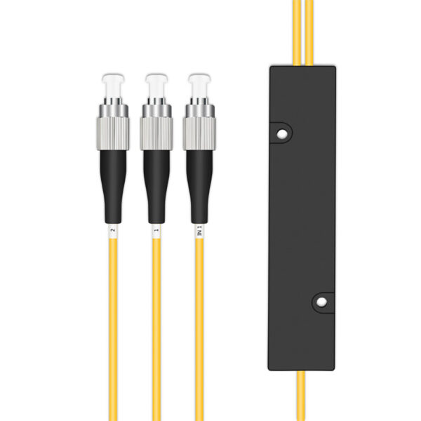
FBT Fiber Optic Splitter Small Box – 1xN & 2xN Options
Price range: $3.00 through $25.00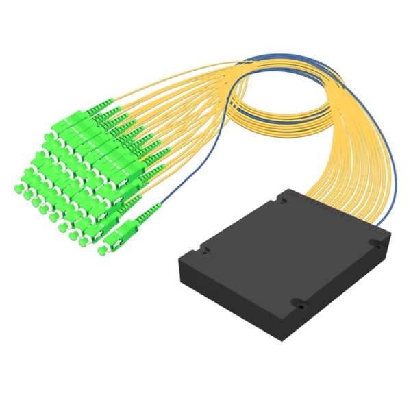
FTTH SC/APC PLC Splitter ABS Box – 1xN, 2xN Fiber PLC Options
Price range: $2.50 through $50.00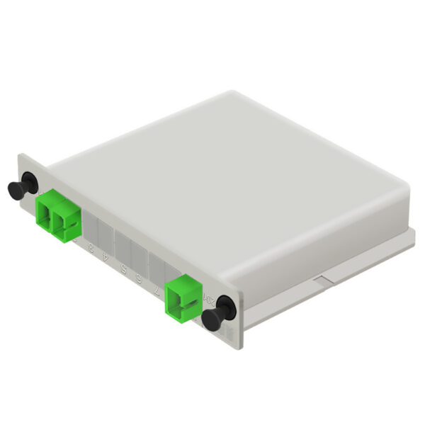
LGX Cassette PLC Splitter – 1×2, 1×4, 1×8, 1×16, 1×32 SC/APC, Singlemode
Price range: $3.00 through $19.00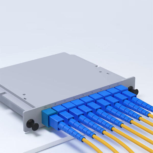
LGX Cassette PLC Splitter Module SC/UPC – 1×2 to 1×32
Price range: $12.00 through $66.00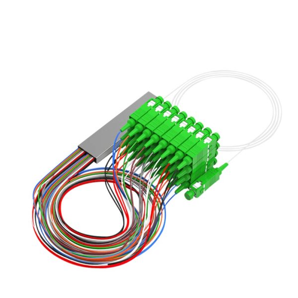
Mini Fiber Optic PLC Splitter SC/APC Connector, 1×2, 1×4, 1×8, 1×16, 1×32, 1×64 Configurations
Price range: $4.90 through $32.00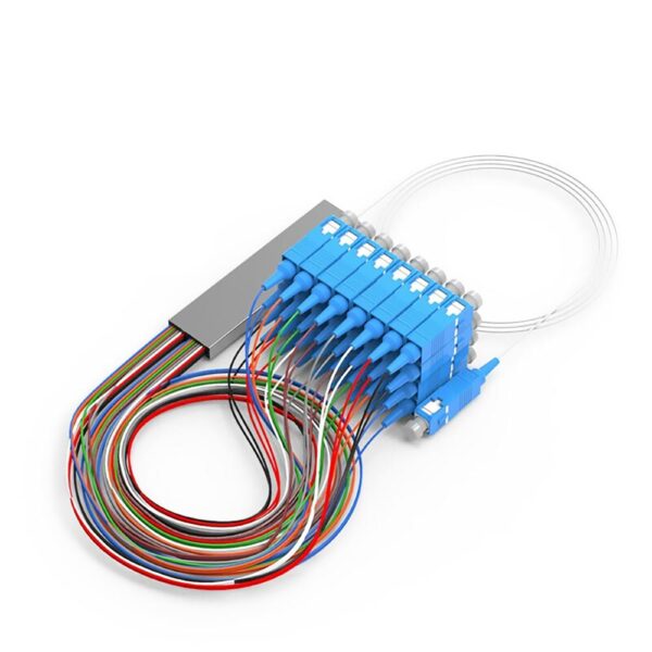
Mini Fiber PLC Splitter SC/UPC Connector, 1×2, 1×4, 1×8, 1×16, 1×32, 1×64, 1×128 Configurations
Price range: $5.00 through $29.80Why Fiber Optic Splitters Are Your Best Budget-Saving Tool
The Core Magic: Understanding the Three Key Technologies Behind Splitters
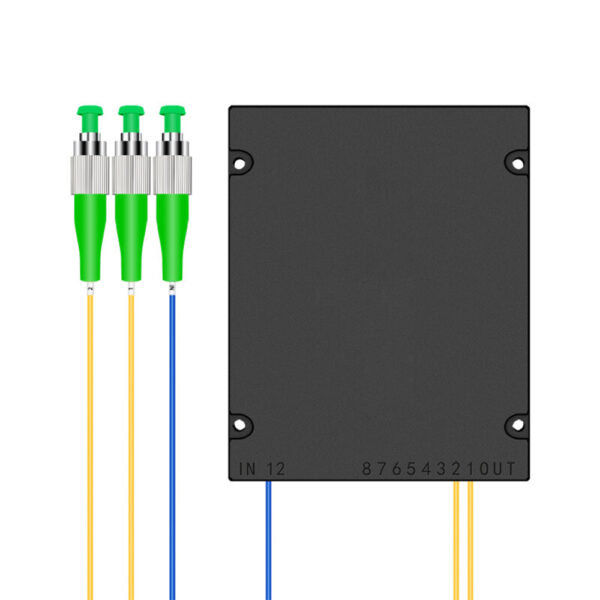
What Is a PLC Splitter? (Chip-Level High Precision Splitting)
A Planar Lightwave Circuit (PLC) splitter serves as a miniaturized semiconductor chip designed specifically for light applications. Visualize a small, flat circuit made of quartz, where light waves can be directed and evenly split; that’s what you get with a PLC splitter! PLC splitters guarantee consistent optical power at all output fibers, along with impressive stability.
A PLC splitter is manufactured using integrated optical waveguide methods, successfully channeling light into input fibers and distributing the light uniformly across multiple output fibers. Compared to older splitters, PLC splitters maintain signal quality better when an individual fiber needs to be split into many outputs. This clearly makes PLC splitters very viable for large fiber optic networks. The principle of compact size and reliability uniquely applies to the types of environments that ISPs and data centers exist in. In summary, PLC splitters provide a stable, uniform, and scalable method for large fiber connections.
What Is an FBT Splitter? (Fusion-Based Low-Cost Splitting)
Fusion-Based Biconical Taper (FBT) splitters work by combining and fusing pieces of fiber together. Picture two craftsmen slowly tapering pieces of fiber while combining their light paths. This design produces a very low-cost geometry, as the ability to split a signal is very flexible and customizable, producing custom ratios such as 40:60 and less than 40:60.
FBT splitters do not have the same level of performance uniformity as PLC splitters; however, they are applicable in small network environments or special splitting ratio applications. The manufacturing process is much simpler, leading to significant value savings for budget-conscious or limited distributions of the product. The performance is not as uniform, and the temperature ranges are not as forgiving; however, they are applicable in networks where advanced splitting is not required.
Quick Visual: PLC vs. FBT Core Performance Comparison
| Feature | PLC Splitter | FBT Splitter |
| Insertion Loss | Low and consistent across outputs | Higher, varies between ports |
| Uniformity | Highly consistent signal distribution | Less uniform, especially with many splits |
| Operating Temperature | Wide (-40°C to 85°C) | Narrower, more sensitive |
| Splitting Ratios | Standardized (1x2 to 1x64), equal split | Flexible, customizable ratios (e.g., 40:60) |
| Price | Higher upfront, cost-effective at high splits | Lower cost for small splits, less so at large splits |
| Use Cases | Large-scale networks, FTTH, data centers | Small-scale, budget projects, custom splits |
PLC splitters work like semiconductor chips for light, providing stable and accurate splits for large installations. FBT splitters join together and taper fibers for use in budget-conscious, smaller installations where customizing a split is needed. PLC provides better performance and scalability, while FBT is a cost-effective solution for simple splitting needs. This will assist SMB admins and internet cafés in selecting the right splitter based on their technical needs and budget.
The Splitting Ratio Magic: How to Choose Between 1x2, 1x8, 1x32…?
Decoding Splitting Ratios: What “One-to-How-Many” Fits Your Network?
The split ratio in a fiber-optic splitter represents the way in which one input fiber is separated into multiple outputs, shown as a ratio—for example, 1x2 or 1x8. A 1x2, for example, is a splitter that divides the fiber into two outputs, with an even distribution of light power into those two outputs. A 1x8 splitter will diverge the light into eight outputs, providing less power to each output.
Deciding on a ratio depends on the size of the network you require. Small networks, for example, smaller offices or cafés, may wish to use a 1x2 or 1x4 splitter, which still provides a very strong signal running through 2-4 outputs to ensure enough gain. Medium-sized networks can utilize a 1x8, with even less gain, to service even larger networks, while maintaining a balanced approach to the number of devices and signal quality.
A higher split ratio does have the ability to accommodate more endpoints on a network; however, it will also diminish fiber power, which can cause many potential performance issues. Using a controlled approach between the number of connections and adequate optical power is ultimately needed to design a stable network. This will allow you to better utilize the resources that are available while providing a means of connectivity.
The Secret of Signal Loss: Why More Splits Mean Weaker Signals
The loss of signal in fiber optic splitters occurs primarily as insertion loss (as the light travels internally in the splitter) and splitting loss (when light is divided from one input to multiple outputs). Insertion loss is simply a measure of power removed from the signal as it travels through the splitter and is represented either in decibels (dB) or as a percentage of the original power.
Splitting loss occurs because when the signal is divided, the signal at each output will experience a reduction in power as it is shared with other outputs. For example, if you have a 1x2 splitter, you will effectively have half the signal power at each of the two outputs (which is about a 3 dB loss). If you have a 1x8 splitter, you will receive about 1/8 of the original signal at each of the 8 outputs (which results in about a 9 dB loss).
From this example, it is clear that more splits or branches will result in a more significant drop in signal strength. In general, if there are fewer splits, the connections made using the splitter will be stronger and more reliable. If there are a higher number of splits, administrators will need to manage their power budget appropriately in order to have a reliable signal at each of the outputs. Understanding the losses due to splitting will give administrators the ability to manage the number of connections they have with the quality of the output signal.
Easy Decision-Making: A 3-Step Guide to Picking Your Ideal Split Ratio
To begin, list the number of endpoints that need to be connected. This will help you determine the splitter size you will need. Next, you should confirm your optical power budget. Power is lost as a result of each split in the signal, and you will want to select a split ratio that will keep the signals at or above the minimum required for proper operation. Longer cable runs or higher data rates may call for an additional safety margin.
Finally, consider the trade-offs between cost and future growth (which is really the trade-off we are considering with a redesign). Higher split ratios minimize the number of splitters required (and therefore also minimize overall cost); however, they increase signal loss and potentially limit future expansion. A split ratio that provides a balance between present needs and future growth will likely involve consideration of not just splitting ratios, but also ease of use. For example, a split ratio of 8 or more would reduce the number of actual splitters needed, but most locations might not have sufficient signal availability for future users if this is not considered when selecting the splitter.
By following these steps, including counting endpoints, managing your power budgets, and considering growth, you’ll be able to select a split ratio that instills confidence in matching current needs with future plans.
Hands-On Guide: Step-by-Step to Building an Efficient Network with Fiber Optic Splitters
From Zero to Hero: Three Easy Steps for Splitter Deployment
Step 1: Get Ready—Choosing Models and Gathering Supplies
Prior to installation, take a moment to gather all necessary tools and parts before proceeding. Be sure to gather fiber optic splitters that are designated for each splitting ratio, appropriate fiber patch and optic cables, as well as cable organizers and cable ties to prevent any tangling.
You will also need some cleaning material, such as fiber connector wipes, lint-free cloths, and canned air. Cleaning the faces of the connector is very important to ensure the maximum signal. As the face of the connector can attract dust, be sure to clean it thoroughly so you do not have any signal loss.
Also, be sure to check that the types of connectors you have (SC/APC vs. SC/PC) are exactly what you need to avoid connection issues. Once you have everything in order, you can proceed with the method you would like to use so that the splitter setup will run smoothly and effectively. It is critical to have all of the necessary components on hand before starting the installation and implementation phase of the splitter process. Having all of the components leads to optimum performance of the splitter, while supporting the efficiency and reliability of the network expansion.
Step 2: The Installation—Making the Connections Right
Begin by taking the main fiber line and connecting it to the input port of the splitter. Ensure the connectors are clean and properly aligned on the fiber line. Avoid sharp bends in the fiber line, as this will cause signal degradation. After that, connect each output from the splitter to whichever device with endpoint devices such as switches, routers, or users. Ensure that you are not mismatching the connector types and that you are connecting to the correct output ports cleanly.
Once you have connected your cables, organize them with cable ties or duct tape; this will help avoid damage, and this can also help keep the cables within their maximum bend radius, which will typically be 30–40 mm. Clearly label cables for downstream maintenance purposes.
Verify all connections and cables for firm and clean connections. This will help to ensure an overall fiber network that is stable, scalable, and organized. Verifying these steps in order allows for a more accurate pathway for future additions.
Step 3: Prevent Problems—Key Installation Details
Abide by the minimum cable bending radius specifications to avoid microbending or damage to the cable that may cause signal loss. A good rule of thumb is a cable bending radius of at least ten times the diameter of the cable after it is installed, and a larger radius to pull the cable.
Keep fiber connectors clean: Dust, oil, or debris may cause insertion loss by blocking the light pathway within the connector. Clean the connectors frequently—ideally, before connecting, cleaning with a fiber wipe or compressed air.
Failure to abide by the cable bending radius or cleanliness protocol may cause permanent damage to the cable and degradation in performance. Careful handling of cables and cleanliness of connectors assures the integrity of the signal at the end device and stability in the network.
Troubleshooting 101: When the Network Goes Down, Don’t Panic!
No Signal? Troubleshoot These Three Most Common Causes
Inspect the splitter's connections and inputs/outputs for any loose connections. Even connections that are a little loose can break the optical path. Be sure to inspect for cable breaks (sharp bends) or damage that blocks light completely. It is important to maintain the proper bending radius.
Clean the connections very well. Remember, dust or dirt can block or obstruct the transmission of light and cause no signal. Restoration of your network can occur quite quickly by addressing loose connections, damaged fibers, and dirty connectors. This will also greatly reduce the potential high cost of network downtime!
Weak Signal? Find and Fix the Culprits of Signal Loss
Weak signal quality can stem from two primary causes: excessively high splitting ratios and dirty connectors.
Combining power into many places provides a weak signal to each of those links. For instance, a 1x32 very high splitting ratio may yield much signal loss. Matching your split ratio with the intended connected devices without dropping below an operational number provides you with better whole system functionality.
Dirty connectors scatter or block light counts and increase insertion loss. Regular cleaning of all connectors on every endpoint or device avoids this issue.
Adjusting the split ratio may help, and as long as the intermediate connections are relatively clean and have good physical parameters, the effect on service in a fiber optic dense network should stabilize and become more efficient.
Compatibility Challenge? SC/APC vs. SC/PC Explained
Properly matching fiber optic connectors is important when it comes to the connection process. SC/APC connectors have the end face polished at an 8-degree angle to reduce signal reflection and are very useful when deploying long-distance, high-precision networks. SC/PC connectors have either a flat or slightly curved end face that reflects more light back down the fiber, resulting in increased return loss.
Connecting an SC/APC connector to an SC/PC connector will cause signal reflections, insertion loss, and data errors, resulting in a less reliable network. Mixing connector polish types can lead to the potential for physical damage to the connector end face.
Always make sure to confirm the correct connector type before the installation process. A common conveyor of information is the color-coded boot system—green for SC/APC and blue for SC/PC—and corresponding labels for the actual cables. Proper matching will allow for low insertion loss and effectiveness of a stable network.
Your Ultimate Tool: Troubleshooting Flowchart at a Glance
To start troubleshooting, check the connections on the inputs and outputs of your splitter. If you still have no signal, check for loose connectors, broken cables, and dirty connectors that might block light. If you have a signal, but it is weak, ensure your splitting ratio is appropriate for your setup. Cleaning the connectors can reduce insertion loss at the splitter. Sometimes, there may be connectors that are mismatched (such as SC/APC vs. SC/PC), which will cause reflections and loss.
This flowchart will guide you through the common issues quickly and return the proper reliability and performance to your network.