Optical Module User FAQs: Quick Answers to User Questions, Reducing Customer Support Burden
Imagine this: It’s 2 AM and your network is down. The monitoring system is showing “optical module failure,” and you are still staring at the error messages without a clue on how to resolve the situation. All of the SFP questions that have not been addressed and the QSFP troubleshooting problems clearly add up to managing so many support tickets. As SFP inquiries continue to overwhelm support teams, requests come in from every customer on issues like module detection, compatibility problems, and signal loss. This all-in-one SFP FAQ provides immediate resolution for some of the more common optical module troubleshooting issues that tie up your support resources. Every common scenario is covered, from vendor coding complexity to fiber type irregularities. We provide actionable next steps. For professional guidance on SFP cleaning and contamination management, see our comprehensive Optical Module Cleaning Techniques and Tool Recommendations guide. This resource helps reduce error reports and unnecessary replacements.
Why Isn’t My SFP Module Being Detected by the Switch?
The limitations on vendor coding are akin to the commissioned bouncers at an exclusive bar. Leading switch vendors build firmware locks that actively disallow third-party modules. In the case of Cisco, HP, and Juniper switches, the usual response is to show a message stating “unsupported transceiver” after recognizing the third-party hardware. This all resembles a handshake protocol that went horribly wrong. In other words, the switch asks the module’s EEPROM for vendor codes. For instance, in the case of a Cisco switch, this prompts questions about whether the hardware has been tested and validated with the switch. Understand more about module detection issues and vendor lockouts in detail at Why SFP Modules Are Not Detected.
The physical connection is often the most overlooked variable in SFP troubleshooting. The modules require alignment in precise proximity to the cage assembly. If the module is aligned, for instance, just 0.2 mm angularly, there will not be contact with the switch backplane. Separate the module suspected of difficulty. Inspect the connector pins for oxidation, debris, or damage. If the module appears okay, then try to clean the contacts with isopropyl alcohol and a lint-free cloth. Reconnect the module again, but turn the module slightly until it firmly seats, and you hear the click of the retention. Learn how to properly handle and install SFPs to prevent hardware damage with our SFP Safe Plug-and-Play Ultimate Guide, ensuring network stability.
Port-level diagnostics can allude to hardware concerns not always directly observable at the hardware level. Different manufacturers have varying methods of port detection verification for modules, and all Ethernet switch ports can fail to their corresponding ports without triggering an alarm. Consider testing the same module in the adjacent ports to determine switch-side faults. Cross-reference the port with acceptable modules you know will work. There are many questions that go back to the modules. The best process is one that takes the guesswork out of things if you have identified the keys about the module internally and if the switch is capable of detecting any unknown module.
Temperature cycling may reset some of the intermittent recognition faults. Power-cycle the switch while the modules are seated into the switch. It could be the thermal expansion that finally re-establishes an already shaky electrical connection that was, in the first place, causing a module not to be recognized when the switch operates normally.
 The Network Engineer’s Nightmare: Mixed Fiber Types and Signal Loss
 The Network Engineer’s Nightmare: Mixed Fiber Types and Signal Loss
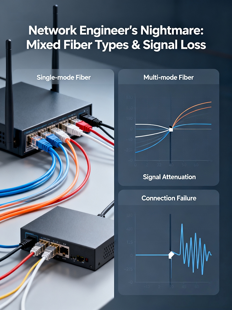
Sarah’s Monday morning began with an inundation of panic calls regarding intermittent drops in the fiber optic network. The new 10GB links Sarah had so carefully installed operated flawlessly for a matter of minutes, only to fail without notification. Then it got worse: in an unpredictable twist, the link would restore itself at random points throughout the day. Who doesn’t love a little mystery on a Monday morning?
So what was the issue? As is often the case, the SFP modules were the source of the problems again. In this case, the SFP modules were single-mode SFP modules attached to multimode fiber optic cables. Using the analogy of trying to aim a laser pointer through frosted glass, the transmission was scattered due to the stitching we observed when we verified the module specs and discussed and inspected the fiber optic cable type. Single-mode modules transmit data across the 1310nm or 1550nm wavelengths over 9 micron core fiber, whereas multimode systems transmit at 850nm across either 50 micron or 62.5 micron core fiber.
Wavelength mismatches in fiber networks result in invisible bedlam! The fundamental incompatibility of single-mode and multimode ultimately caused signal attenuation as it was affected by temperature and vibration, resulting in unpredictable link behavior.
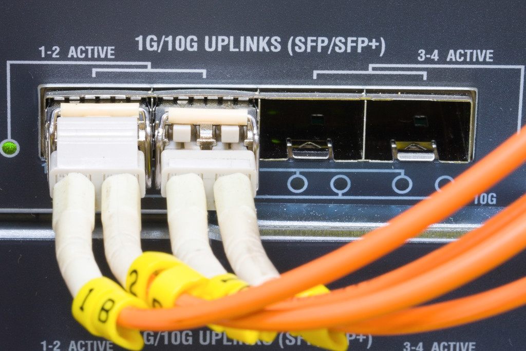
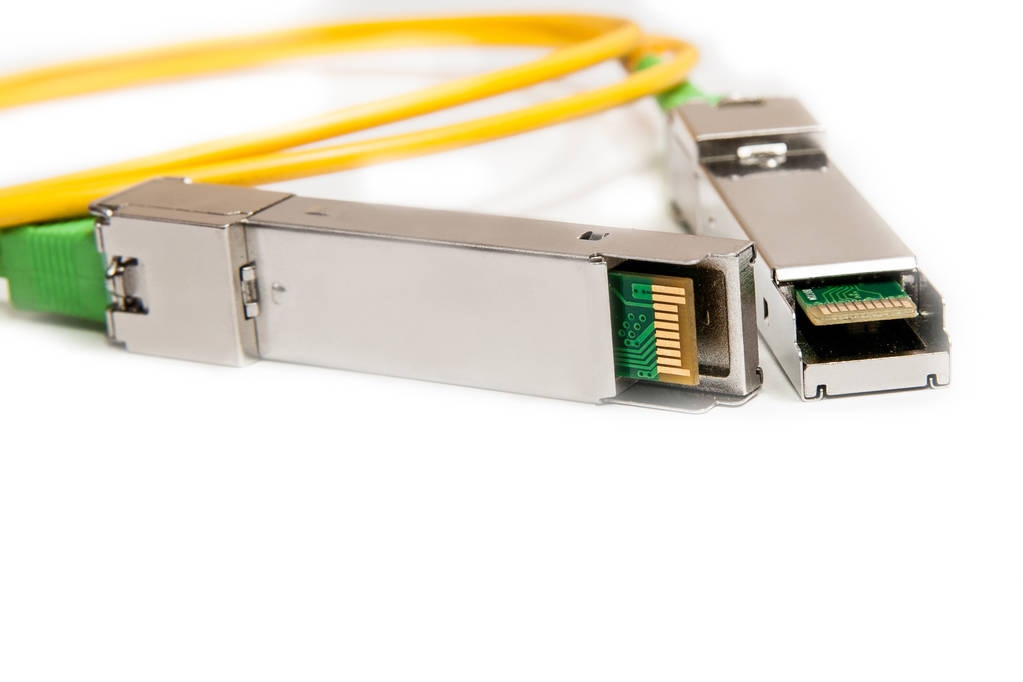
A simple visual inspection could have easily identified this costly SFP troubleshooting scenario. Optical fiber cable jackets that are yellow denote the presence of single-mode fiber with 9 micron cores. Conversely, optical fiber cable jackets that are orange or aqua denote the presence of multimode fiber, either with 50 micron or 62.5 micron cores, respectively.
In addition to the optical fiber jacket colors, connector colors provide another clue to help verify compatibility of fiber and modules. Blue connectors are generally associated with single-mode cables, while beige connectors are an indicator of multimode fiber. However, some manufacturers use different color schemes; therefore, conducting a visual inspection of the cable jacket is more reliable.
Referencing the manufacturer’s module specifications and revisiting the fiber type will eliminate guesswork when assessing the cause of the issue: single-mode SFP modules must be used with single-mode fiber, and multimode modules must be used with multimode fiber. Using a combination of the two guarantees unpredictable SFP troubleshooting scenarios for network engineers and network users! For detailed protocols and cleaning strategies, consult Optical Module Maintenance and Cleaning.
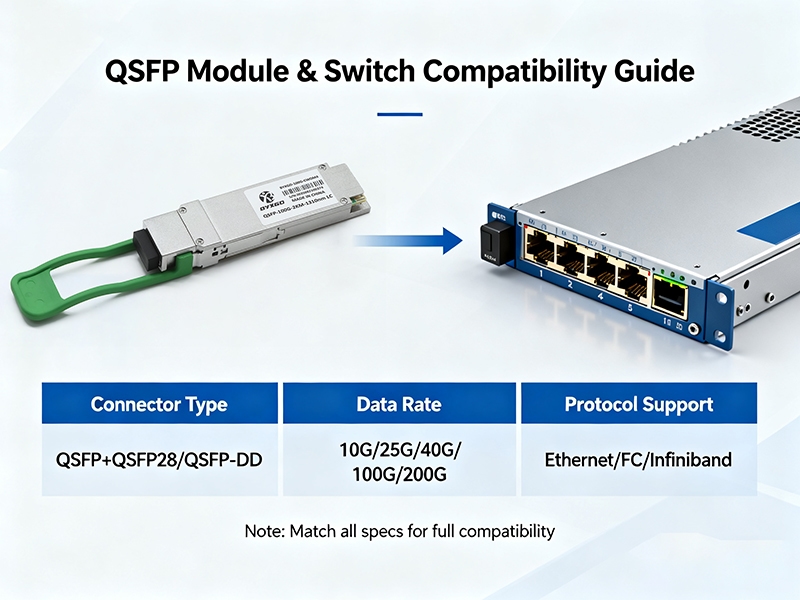
How Do I Know If My QSFP Module Is Compatible with My Switch?
The evolution of QSFP standards is comparable to generations of smartphones, where each newer version provides additional capabilities but still presents concerns with backward compatibility. While QSFP28 modules support speeds of 100G, QSFP+ modules are limited to a maximum throughput of 40G, and the original basic QSFP standards provided a maximum throughput of 4x10G.
One of the most common topics in the QSFP FAQ is the failure of breakout cables. A QSFP+ to SFP+ breakout cable splits one 40G port into 4, 10G connections. Many switches require specific commands to be entered in order to enable the breakout capability.
Different switch vendors provide different approaches for supporting QSFP compatibility. For example, the Cisco ASR9000 series supports the use of QSFP28 modules but limits certain third-party options through the use of firmware validation, and Juniper EX4600 switches support the use of QSFP+ modules but restrict the use of breakout cables to specific ports. Compatibility matrices take away some of the guesswork of QSFP compatibility for switch administrators. Understand the importance of POE support and power considerations in switches with Why SFP POE Switches Matter.
For example:
- Cisco Nexus: QSFP28/QSFP+ supported, breakout requires interface configuration
- Arista 7050: Native QSFP28 support with automatic breakout detection
- HP FlexFabric: QSFP+ compatible, requires manually configuring breakout cables
Lastly, form factor differences introduce a physical issue that might come up during installation. While QSFP28 modules take up the same cage as QSFP+ modules, different heat signatures are produced. If a switch’s cage is densely configured, concern for cooling increases with the different switch module types. Explore the critical role of pinout configurations on installation success with Why SFP Module Pinouts Matter More Than You Think.
One more consideration is the firmware compatibility that exists internally during QSFP troubleshooting scenarios. If a switch is running firmware that is incompatible, a switch may reject a QSFP28 module based on supported firmware, even if the compatibilities are true. Always double-check to make sure minimum firmware requirements are confirmed when looking to deploy a mixed QSFP environment.
Database Backup Failures: When Temperature Kills SFP Performance
Marcus found himself in a nightmare. The database would fail during backups every time between midnight and 4 AM. After formal investigation and changes, there were no issues with storage, data processing, or network congestion. The only logical factor was attributed to temperature in the server room where the SFP modules were located. Every time the server room had active cooling during peak hours, the laser module was drifting out of operational specifications due to temperature changes. Learn how temperature impacts SFP performance and lifespan by reading our Ultimate Guide to SFP Module Temperature.
The performance degradation from temperature is well-known and often likened to operating an automobile engine during extreme temperatures. Laser diodes in SFP modules are no different. Whenever the operating temperature exceeds ~70°C or the operating limits, the wavelength drift will occur and degrade the optical transmitter links. Any fluctuations in operating parameters cause degradation, and link stability issues occur as the thermal stresses continue to accumulate during a daily thermal cycle. As the temperatures rise, the laser threshold current rises, even exponentially. Increasing the laser threshold current leads to decreasing output power and exceeded lifespan of the SFP components.
SFP modules display predictable patterns of performance degradation under temperature stresses and rising temperature. For example, a known 10°C increase in temperature generally translates to a -0.1dB drop in receive sensitivity. The transmit power output decreases with increased temperature, causing asymmetrical link performance and creating confusion about SFP component failures.
Other variables surrounding the installation are attitudes and worsening temperature-related degradation. Variables such as active cooling and strenuous planned and unplanned maintenance behaviors involving HVAC installations and cleaning crews develop thermal gradients, as air is moved through the confines of the rack and other factors create ‘hot spots.’ Typical methods of cooling often lead to an additional 15-20°C temperature rise. Therefore, there are other variables that, in specific assemblies, would lead to thermal imbalance and inaccuracy detailing the SFP installation, given established and ideal expectations that were communicated.
The vibration from cooling fans causes disruption as an additional stress vector on SFP modules, increasing performance degradation. There is loosening of electrical circuits from micro-vibrations caused by the aforementioned HVAC systems that cycle on and off, which over time loosens electrical connections. The compounding impact of temperature cycling within these assemblies will further lower the lifespan of optical components.
Dust will accumulate within the SFP cage assemblies, causing thermal insulation. This dust either restricts airflow or builds up over time to cause inadequate airflow for sufficient heat dissipation. When dust or insulation occurs, increased temperatures will frequently push and exceed individual modules and their components beyond their generally “safe” operational limits during peak periods when the modules are consuming the most power and operating at their maximum bandwidth capacity.
These facts lead to the question of what constitutes acceptable optical power in a fiber link based on the types of applications on the same point. Short-reach modules usually have a general use range of approximately -14dBm and +1dBm receive sensitivity. Long-haul SFP style modules will be required with additional tolerances to provide error-free transmission quality that is maintained over longer distances.
What Do These Cryptic Error Messages Mean and How Do I Fix Them?
“RX_LOS” means “Receive Loss of Signal” – meaning your SFP module stopped seeing light from the other side. Imagine your flashlight has dead batteries and is shining in a dark room. Generally, a physical fiber disconnection or very low power will cause this alarm to go off every time.
“CRC errors” means something interrupted your data during transmission, sort of like static on a radio station. Numerous CRC errors, in particular, mean you might have lower signal quality than what you’re used to, but it doesn’t necessarily mean the link is broken completely. Usually, environmental factors such as temperature spikes or vibration will cause CRC error bursts.
“Transceiver not supported” means the vendor lock-out mechanisms failed, and the SFP module does not recognize third-party vendor code. This is actually a configuration issue that needs to be fixed by an admin, not hardware replacement. Switch firmware is intentionally blocking third-party transceivers through vendor code because it’s been explicitly told the module it checked was not factory specification compliant.
“GBIC invalid” indicates switches detected no electrical communication from the SFP module’s EEPROM. GBIC invalid errors are a commonly-generated SFP troubleshooting state caused by corrupted module identification data or, even more frequently, simply a loose physical connection.
Not all configuration errors alert users through hardware patterns or flaws. Vendor compatibility issues will cause the device to consistently reject the module immediately after it’s inserted. On the other hand, hardware degradation will cause the system to become increasingly unreliable with intermittent error reporting, and the pattern will worsen over time.
While the error state clearing procedure will vary from manufacturer to manufacturer, the process between them will follow a similar pattern. When it is imperative to power cycle an affected interface through the administrative shutdown / no shutdown commands, a communication timeout issue will generally resolve. In a similar manner, removing a physical module and reinserting it will reset the electrical connections and cause the device to clear persistent error states.
In short, hardware failure is indicated when error frequencies get worse and you have controlled environment factors at the same time. At that point, just do your customer a favor and put in a replacement module showing continued network degradation instead of wasting time trying to reset faulty component functioning, which doesn’t allow you to continue with an SFP troubleshooting document.
The $500 Lesson: Preventing Long-Distance SFP Module Burnout
David made a costly mistake in just a few seconds by connecting two fully functional 80km SFP modules directly together using a patch cord to “do some quick testing.” The high-power laser output from one module instantaneously overloaded the sensitive receiver of the other module. $1,000 of specialized equipment was rendered non-usable and became pricey paperweights.
Optical input overload destroys receiver photodiodes similar to how staring directly at the sun damages the human retina. Long-distance SFP modules transmit at power levels of +5dBm to +8dBm to combat fiber attenuation over longer distances. Standard receivers expect to receive maximum levels of -3dBm to -1dBm to operate safely. The power differential of 8-11dB instantaneously saturates the photodiode and causes irreversible damage to the receiver.
Creating a direct connection between high-power sources and sensitive receivers creates a power mismatch due to exceeding acceptable limits. The use of an optical attenuator to reduce the amount of signal strength is required before connecting a long haul module in a back-to-back configuration. A fixed optical attenuator that yields a 10-15dB loss will help prevent an immediate overload condition, damaging the photodiode.
Digital Optical Monitoring protects from power overload scenarios in real time. SFP modules capable of generating DOM report transmit power, receive power, temperature, and bias current through EEPROM registers. Dynamic monitoring and reporting of modules will help alert human intervention and keep costly SFP issues at bay, which are often linked to sudden module failure.
Alarm thresholds will trigger and alert users to dangerous conditions. If the receive power is observed to exceed -1dBm, sensors will also trigger a helm, a condition that needs immediate attention given the overload to the receiver. Transmit power less than specification may result in laser failure or thermal shutdown protection being activated.
This article explained preventative measures that will protect against accidental damage in the mounting and testing process. Always confirm that power levels are compatible before a direct connection is made. Ultimately, the best solution is to attach an optical power meter to verify the actual output levels and not just rely on each respective module’s output specifications.
Use variable optical attenuators for additional adjustable protection, especially for attenuation experienced with mixed distance SFP deployments that have to meet different power budgets throughout a single network infrastructure.
 Top 5 SFP Issues That Generate 80% of Support Tickets
 Top 5 SFP Issues That Generate 80% of Support Tickets
Analysis of internal tickets reveals predictable patterns of customer issues that are overwhelming support queues. Five problems make up about 4,200 tickets monthly per enterprise customer. The resolution complexity varies greatly, from issues resolved through self-service to those requiring the intervention of an expert.
Vendor compatibility rejection problems take up the majority of the ticketing landscape, with 1,680 ticket submissions every month. Vendor compatibility rejection issues average a resolution time of 45 minutes when customers have sequentially brief access to the command line interface. The self-resolution ratio appears to be 85% when customers have access to proper documentation.
Fiber type mismatches average 840 tickets monthly, with an average resolution timeframe of 30 minutes for the category. We found that visual identification training for fiber type mismatches reduces repeat tickets by 72%. The majority of customers resolve visual fiber type issues after they have been shown how to identify them during the first call.
Connection seating challenges average 672 tickets every month and require a 15-minute resolution time frame. We observed that training the customer to perform physical, on-installation checks appears to minimize repeat tickets for connection seating issues. The customer may be able to perform minor cleaning procedures and solve 60% of their component connection seating issues without the need for technical support.
| Issue Category | Monthly Tickets | Avg Resolution | Self-Service Rate |
| Vendor Compatibility | 1,680 | 45 minutes | 85% |
| Fiber Type Mismatch | 840 | 30 minutes | 78% |
| Physical Connection | 672 | 15 minutes | 90% |
| Error Message Decode | 504 | 20 minutes | 65% |
| Power Level Issues | 336 | 60 minutes | 35% |
Preventive education makes a huge difference in support effectiveness. Customers who receive preventive education training, on average, submit 67% fewer tickets over a 12-month window. In addition, having full SFP FAQ documentation helps reduce escalation rates as well as improve first-contact resolution rates for any remaining customer tickets that require escalation for human interaction.
The IT Manager’s Midnight Emergency: Clean or Replace Decision Matrix
 The IT Manager’s Midnight Emergency: Clean or Replace Decision Matrix
At midnight, Rachel experienced her worst nightmare when critical production links failed as part of system upgrades. In consideration of $50,000 in revenue loss per hour, it was a matter of making decisions quickly about cleaning contaminated modules or replacing them with emergency spares to keep the business afloat.
I refer to the visual indicators of contamination as immediate diagnostic indicators that inform decision-making for SFP maintenance. If I see brown or black deposits on the connector face, environmental contamination is indicated, and a cleaning procedure is warranted. If the ceramic ferrule is cracked or the connector pins are damaged, replace the module immediately because it is permanently damaged.
Module performance degradation patterns allow us to distinguish recoverable module conditions from fatal module conditions. For example, if intermittent connectivity is present with high error rates, those modules generally respond to cleaning. If there is no signal and the optical power is reading zero, the module’s laser has failed and will need to be replaced.
Cost-benefit analysis favors cleaning a module if the module is less than 18 months old. The supplies needed for cleaning cost about $15 per incident, while replacing a specialized module will range from $200 to $800. Typically, if the performance issues are related to environmentally induced contamination, we have had a success rate of greater than 75% in resolving performance issues with cleaning.
The time-sensitive nature of the issue changes the decision matrix in these emergency situations. From an operational perspective, a mission-critical application could require a replacement module installation instead of waiting 30 minutes to see if cleaning resolves it. Time is relative, but on occasion, you could have a spare module to insert while cleaning.
| Symptom | Cleaning Success | Replacement Required | Decision Time |
| Visible dirt | 85% | Rare | 2 minutes |
| Intermittent errors | 70% | 30% | 5 minutes |
| Complete failure | 20% | 80% | 1 minute |
Emergency procedures always prioritize safety and the restoration of networks over optimizing the lifecycle of modules. When successfully troubleshooting an SFP (small form-factor pluggable) module, you must balance the immediate operational needs of the network against the longer-term strategies of capital investment in equipment to ensure ongoing network performance.
Conclusion
By planning for prevention, you can take systematic measures to reduce the volume of basic, routine support requests. Research compatible vendors, so SFP modules are tested for rejection accuracy prior to replacement. Train your users to identify MTP or LC-type frayed fiber connections to prevent replacing SFP modules that are perfect, just mismatched splice applications.
Priorities for adding to the seamless experience: Train user groups, company-wide or local, to improve basic SFP troubleshooting for the top five contributors of volume support. Create and distribute decision matrices to mitigate emergency response scenarios and costs as much as possible. Take into consideration a plan to have a technical breakdown of the overall cost of the SFP, but also include prior funding decisions once the SFP is deployed in the field and usage begins. At what average threshold will the five vendors’ DOM become worrisome, and replacement should begin?
Shift the operational efficiency for support by planning a preventive module management solution and reduce reactive support that can use unnecessary resources and frustrate your user customers.