Optical Module Coding Explained: Why Compatibility Matters and How to Diagnose It
In an environment where speed and reliability are a must, optical modules are important, but the real power rests on one key factor that is often overlooked: coding. This single digital fingerprint ensures that all devices work without errors. Understanding optical module coding brings more than easier integration; it will help you troubleshoot more intelligently and reduce risk. Let’s discuss how mastering coding can improve your network’s stability, efficiency, and even allow you more foresight to diagnose problems and prevent costly interruptions before they happen.
What Is Optical Module Coding and Why Is It the “Digital Key” to Compatibility?
The optical module coding acts as a digital fingerprint that is inscribed into each transceiver’s EEPROM—a memory chip. This fingerprint reveals important information including speed rating, wavelength, supported distance, and power levels. You can think of it as an ID card that helps network devices, especially switches, quickly identify what kind of module is connected. When an optical module is plugged into a switch, the switch first reads this code to see if it is an acceptable code.
After the optical module’s code is read, the switch determines if the code fits what it’s expecting. If the code is what it is expecting, then the module will work without an issue, but if the code does not match what the switch expects, the switch will either reject the module or indicate it is having issues supporting it. Again, the purpose of this compatibility check is to ensure that the module is suitable to maintain the stability of the network.
In essence, optical module coding acts as a lock-and-key system (i.e., the code is the “key” to unlock proper communication), where if the switch likes the specifications of the transceiver, it will allow the module to connect. Without an appropriate digital key, the optical modules may look and feel the same, but they will not work correctly (as the switch won’t trust the specifications). This is why accurate coding is of paramount importance, as it applies to SFP coding, optical module coding, and maintaining network reliability.
Why Do Vendor-Specific Codes Create Compatibility Locks?
The Multi-Source Agreement (MSA) has set the stage for industry standards for optical modules by establishing standards that allow for basic interoperability across multiple brands. However, the basic standards allow vendors to add their own proprietary code to each module’s EEPROM that creates compatibility locks on modules, subsequently locking modules to work only with specific equipment, similar to how car keys only work for specific vehicle models.
Vendors have their own unique identifier—as well as vendor-specific fields—that are validated by the switch when a module is authenticating. If the compatibility code is not an exact match to what the switch expects, the switch will reject the module even if the module is technically compliant. By doing this, vendors limit competition and lock end-users into only purchasing from that vendor.
Cisco provides a great example of this practice. Cisco switches will validate their proprietary codes and only allow Cisco-branded or certified modules to run without warning, and ports will not be disabled or shut down. If the third-party module does not have Cisco’s exact coding system, the switch may disable the ports or produce an error, which could impact any group relying on the network for uptime.
In short, vendor-specific coding is a digital lock that ensures the vendor’s modules are compliant with their brand locks. While the MSA may promote standards-based modules, proprietary fields provide opportunities for vendors to limit the availability of compatible modules in the market as they control the module. Therefore, MSA-established vendors and their SFP coding are especially important for organizations managing multi-vendor environments.
What Are the Main Transceiver Coding Types and How Do They Influence Compatibility?
Transceiver coding utilizes recognized standards that detail how modules communicate relevant configuration information. For example, two standards of coding are SFF-8472 and SFF-8636. Both SFF-8472 and SFF-8636 define how the swapped EEPROM data is structured, but the purposes are different.
SFF-8472 describes basic diagnostics and the ability to report identification information, such as speed, wavelength, and temperature monitoring. It also allows modules to report minimal status information essential for reporting on network health and provides some examples of vendor-specific capabilities.
SFF-8636 introduces improved memory maps and allows interface types (for example, pluggable) and additional vendor details; it also supports newer modules that need vendor-specific interfaces or other details that were properly spec’ed relative to clearly demarcated purposes. On the one hand, the SFF-8636 standard provides better control and improved features, the downside being it is less amenable to compatibility across different vendors.
For all the differences in the coding types of transceiver modules, levels of compatibility can differ. Thus, if a module is designed under an older or simpler coding standard, it will arguably provide wider compatibility, while if it follows the advanced standards, it is likely to be held to stricter checks against other modules. At the end of the day, the differences in coding matter for how easy different brands or modules are to work together, making coding details very important when choosing modules for shared environments, as resolving compatibility issues is usually a chaotic experience.
How Can Coding Mismatches Trigger “Unsupported” Errors and Affect Network Stability?
Switch firmware acts as a strict gatekeeper, checking the code of the optical module being used each time a new transceiver is plugged in and then comparing the code to a whitelist of valid values. If the code does not match an approved value, the firmware will trigger an “unsupported” error.
More often than not, user interface errors will lead to a shutdown of ports or warning alerts that indicate a locked-out device. In this case, the firmware will be actively blocking the optical module to protect the network from potential instability. Other issues due to coding mismatches (such as link flapping, failed negotiation, or degradation) would still prevent the module from operating.
One real-world example not specific to Cisco is that other switch vendors, such as Juniper, will trigger similar errors, excluding third-party optical modules that do not exhibit an exact coding match.
In summary, incorrect optical module coding can create challenges for network performance by blocking the recognition of the device and disrupting communication. All of this speaks to the importance of ensuring precise SFP coding to help ensure devices will operate properly.
How to Decode and Interpret SFP Module Codes Like a Pro?
To understand the SFP module code, we simply have to decode key fields that are contained in the module’s EEPROM, like pieces of a puzzle revealing what the module is and what it can do.
Let’s start with the Vendor ID. This confirms who made the module and lets you know whether it is an OEM or third-party compatible module.
The next important field is the Speed Code. This is usually presented in Gbps. For example, a module will have a label of 1G, 10G, or 40G. The Speed Code is the maximum data rate the module can support.
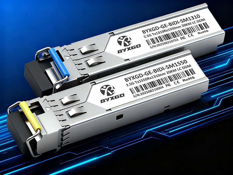
Following the Speed field is the Wavelength field, usually represented in nanometers (nm), such as 850 nm for short range (SR) or 1310 nm for long range (LR). The Wavelength must match the optical fiber specification, so make sure this is in agreement with your network requirements.
The last field is the Distance Code. The Distance Code indicates the maximum distance supported, for example, is it 300m or 10 km? Always make sure you are matching distances, as the optical module will have difficulty transmitting the signal if there is a mismatch.
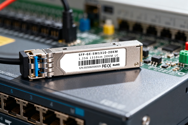
For example, if the SFP module label shows Vendor ID: Cisco, Speed: 10G, Wavelength: 1310 nm, and Distance: 10 km, this confirms the module is suitable for 10G long-distance links in Cisco-compatible devices. If any of these fields were different, the function of the module may have a distance or compatibility issue.
It is very simple to decode these fields, and only 4 pieces of information take the guessing out of what the SFP will do for you. In addition, using this information will likely make the troubleshooting steps faster by identifying where the mismatch or error occurred in the optical module coding.
What Are the Top Warning Signs Indicating Coding-Related Compatibility Problems?
Errors in the coding of optical modules often produce some telltale signs to indicate compatibility issues. One of the more common messages is “unsupported transceiver,” indicating the respective switch has refused to accept the module because the module’s coding does not match approved values.
Another common symptom is link down, or often intermittent drops in the link. This generally occurs when the module’s specifications do not conform to the accepted specifications, thus returning a non-negotiation or an unstable link.
A less noticeable but still very important symptom involves temperature issues. Some modules will report odd or unusual temperatures relative to the specifications of the module due to improper coding or, occasionally, simple missing code.
Both of these coding issues can often cause unnecessary alarms or lead to a forced shutdown. By paying attention to symptoms and logging these symptoms early, it is easier to pinpoint the coding problems before they affect the network.
Watch for error messages in the device logs, unusual or unexpected port behaviors, or sudden network outages. All are signs that coding for the optical module may be an issue.
How to Conduct a Systematic Troubleshooting Workflow for Coding & Compatibility Issues?
When dealing with optical module compatibility or coding challenges, having a specific workflow can help you get to the root of the problem without much hassle.
First, reboot the port or device that is affected by the optical module. Sometimes, a device incorrectly reads the coding from the optical module, and simply restarting the port or device performs a refresh and will take care of minor errors.
After rebooting, check the physical connections to make sure the fiber isn’t damaged and is properly seated. Having a clean and strong connection allows the optical module’s EEPROM to be read correctly.
Third, use CLI commands to print and retrieve the module’s information so you can examine the EEPROM data. Information will include vendor ID, distance code, speed, and wavelength.
This checks to see if the switch is able to read the digital fingerprint of the optical module or is reporting that it is incompatible. If the information appears to be incorrect or inconsistent, compare the coding that you see with published or known codes from the manufacturer.
When in doubt, replace the optical module with one that is known to be compatible, and see if the issue travels with the optical module you removed. This will ultimately indicate whether the coding fault is in the optical module or something within the switch hardware.
Finally, loop back to logs and alerts to see if there are repeating errors, such as unsupported transceiver or link down, that will often directly relate back to the coding issue.
Following an ordered approach is similar to being a detective, matching symptoms to clues to get to the coding problem in an efficient manner that reduces downtime and avoids being thrown off by a misdiagnosis.
The use of a workflow allows for exhaustive checks of SFP coding and compatibility before pulling hardware out just for the sake of doing so.
How Can CLI Commands and Diagnostic Tools Help Verify Module Coding and Link Health?
When dealing with optical module compatibility or coding challenges, having a specific workflow can help you get to the root of the problem without much hassle.
CLI commands provide a flat way to examine optical module coding as well as link health. A vast majority of vendors, like Cisco, Juniper, and Arista, provide commands to check the EEPROM information, which is stored in transceivers.
On Cisco devices, the command show interfaces transceiver detail reveals important information, like vendor ID, speed, wavelength, optical power, and temperature.
The result of this command gives you information to check against the module expected by the switch.
Juniper switches provide similar output with the show interfaces diagnostics optics command, which includes parameters for receive and transmit power and temperature.
Juniper’s additional parameter power levels give an option to more easily identify issues created from incorrect coding.
On Arista devices, you can again obtain a similar result with show interfaces transceiver. Either way, this CLI command provides a clear means for examining status information and coding details of the module.
While native CLI commands do provide insight into the transceiver, there are third-party tools like EEPROM readers or EEPROM programming software that offer the ability to extract, review, or even reprogram the module coding if needed.
These tools are especially useful if troubleshooting compatibility issues or verifying third-party modules.
In conclusion, whether through CLI commands or diagnostic third-party utilities, you have a considerable toolset for confirming SFP coding accuracy for operational performance all within a network with many components, all while ensuring a stable, error-free optical connection.
What Exclusive Troubleshooting Flowchart and Quick Reference for Coding Fields Can Streamline Diagnosis?
A simple troubleshooting flowchart helps troubleshoot coding issues with optical modules. First, check for physical connections and restart ports.
If you still have errors, check for codes on your modules using CLI commands.
Then compare key coding fields:
- Vendor ID: to determine if it’s a real module
- Speed: to make sure speed matches the network
- Wavelength: confirms the fiber is compatible
- Distance: which matches the link length
If any do not match, scale up the trouble with a known-good module. Logs and alerts may provide additional information.
How to Manage Optical Module Coding Compatibility across Multi-Vendor Environments?
In a multi-vendor environment, coding compatibility of optical modules is largely a management issue and needs to be preemptively planned for.
Mismanaging multiple vendor optical module coding compatibility can be costly. Start with robust and distinct purchasing policies stipulating the acceptable vendors and coding standards so all optical modules purchased are consistent with how the remainder of the network was built.
With your policies in place, engage in successive communication with the vendors, instructing them to provide you with the requested coding information prior to the purchase.
This awareness aids clarity and avoids surprises, which leads to proactively identifying coding information that is not compatible with an SFP module before deploying it.
Inventory management of the optical modules is also critical. Label all optical modules with the coding type, vendor name, and specifications.
Store compatible and certified optical modules separate from third-party modules to reduce the chances of mixing incompatible optical modules during deployment of the physical layer.
Furthermore, conducting regular audits of optical module coding and compatibility will support continued stability across your network.
Treat the coding compatibility similarly to how you would manage the life of an asset, and as an equally important consideration that includes long-term expectations of firmware or physical hardware stability in a multi-vendor network integrated environment.
By remaining disciplined to prevent mixing of vendor coding optical modules, you will minimize downtime and support a hard asset investment.
Why Are Third-Party Modules Risky and How Can They Be Used Safely?
Optical third-party modules can provide cost savings, but there are risks that come with the unpredictable or incorrect coding of those modules.
Third-party optical modules may lack standard SFP coding–making them unstable, unreliable, or incompatible–and lead to network errors like link drops or “unsupported transceiver” messages on a console if installed improperly.
Using optical third-party modules is not complicated if you are cautious. Start with this checklist:
- Use reputable suppliers with proven track records and reviews
- If possible, verify coding is correct by checking EEPROM data with CLI tools
- Perform smaller tests on links before wide implementation
If you complete these steps, you will reduce the chance of surprises, and the third-party modules will be more likely to act as you intended (as an equivalent to a branded module) without disruption to the network.
It is not unreasonable to use third-party modules to save costs, but ensure that your usage is more like the act of using experimental parts until you validate them to decide if you can balance the cost savings versus the new operational risks you are introducing to your network environment.

What Are the Risks and Ethical Considerations of Re-Coding Optical Modules?
Re-coding optical modules involves altering the EEPROM data to duplicate the original equipment manufacturer (OEM) coding. This can allow module interoperability, but there are notable risks involved.
The most obvious consequence is a voided warranty, as many manufacturers will not service the re-coded module.
Another risk to consider is potential issues with firmware upgrades to the switch. The switch firmware may recognize that the module’s code has been altered, which can result in erratic behavior or loss of support.
The last thing a network manager needs is for a module to start malfunctioning unexpectedly after a firmware update, or even a report on replenishment.
Legal issues exist as well. Re-coding any module may infringe on intellectual property rights or vendor agreements. Any violation can leave an organization liable.
After examining and carefully considering these issues, decision-makers must then weigh mitigating cost savings against known and unknown risks.
Using OEM or certified third-party modules, while they may not be the cheapest option, will significantly ease concerns about performance and compliance.
Re-coded modules should only be considered or used if organizational policies allow them as an option, and only after careful due diligence is undertaken to understand the risks associated with the re-coded modules.
Understanding risks allows for better decision-making with respect to the stability and functionality of the optical network and the legal implications for the organization.
Conclusion
Ability and knowledge of optical module coding are necessary for network reliability and cost control.
Being informed about the nuances of coding compatibility helps avoid unexpected system outages and link loss.
The skill set for troubleshooting enables individuals to quickly identify and resolve optical module coding issues, thereby reducing downtime.
The responsibility of management—such as vendor procurement, testing, and inventory management—will help mitigate risks associated with multi-vendor environments.
The combination of these approaches will provide an adaptable and reliable foundation for your optical network.
Considering optical module coding as an important aspect of the optical network empowers network professionals to keep systems operating dependably and predictably with highly heterogeneous systems.
Reference Sources
- Multi-Source Agreement (MSA) Group. Multi-Source Agreement for Optical Transceivers.
- Optical Module Compatibility Code: Unveiling The Key To Seamless Connectivity
- SFP and Optical Module Compatibility Guide
- Transceiver Diagnostics and EEPROM Information