Industrial LAN Cables: High-Speed Standards and Smart Manufacturing Applications

According to a study published in Automation World, manufacturing floors with outdated industrial LAN cables show as much as 47% more unplanned downtime due to intermittent network failures and jitter-related motion control errors. Smart factories need LAN cables that provide microsecond determinism while remaining reliable in challenging industrial environments. The impact of choosing the wrong cable for an application can cost manufacturers thousands of dollars per year in lost productivity, as vision systems fail to deliver critical frames, motion controllers lose synchronization, and production lines completely stop running for unknown reasons. Fortunately, if you are a manufacturer, there is a solution. For a more comprehensive overview of cable construction, performance limits, and challenges in industrial environments, refer to this detailed guide on how industrial Ethernet cables support high-speed big data transmission.
You can choose the correct high-speed Cat6A S/FTP cabling, equipped with M12 X-coded connectors and TSN compliant, to capitalize on all these turnkey failure points. Determinism provides data flows without cycle time variances, while the improved shielding greatly reduces EMI shutdowns in close proximity to VFDs and welders. In this white paper, you will discover the high-speed connecting standards that enable you to achieve ten gigabits per second of reliable data streams in industrial applications, how TSN scheduling guarantees real-time coordinated communications between robots, and understand the selection criteria of industrial cables and connectors that can be used to address or mitigate costly failures in the field.
Finally, you will better understand the specific specifications in industrial LAN cables that fit the demands of your manufacturing environment, including IP67-rated M12 connectors for washdown areas and specific drag chain cables in robotic applications. The outcome? Significant reduction in downtime, increased quality of products, and near seamless integration of IT/OT networks where legacy systems are supported within environments that have embraced advanced Industry 4.0 technologies. For insights on securing these converged networks in industrial IoT environments, review the latest perspectives on industrial networking cables security in IIoT.
What High-Speed Industrial Ethernet Standards Are Essential for Deterministic Control?
Industrial LAN cables need to strike a balance between raw throughput and perfect timing. Important standards determine if data arrives neatly or sloppily. Educating on these specifications will help prevent costly mistakes on the factory floor. Going beyond basic connection requirements uncovers what really sets performance apart.
From Office Cat6 to Factory Cat6A + M12 X-Coded: Why the Physical Build Guarantees 10 Gbps Near Motors
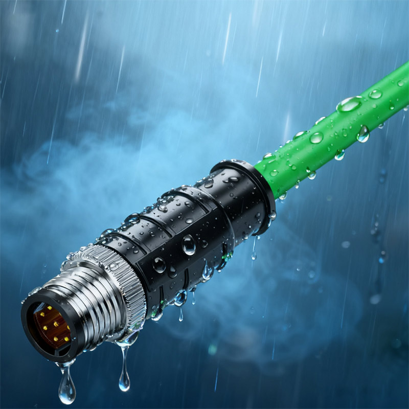
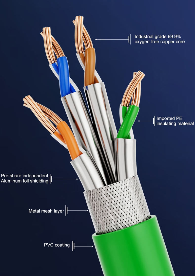
The screened/foiled twisted pair (S/FTP) design encloses each twisted pair and the entire cable assembly in a shield of foil and braid for electromagnetic noise immunity against variable frequency drives or welders. The jacket is 360° continuous, ensuring EM noise isn’t allowed to break through at any connector termination. The M12 X-coded connectors incorporate four Cat6A pairs, housed in an IP67/IP68 sealed shell designed for washdown or high-vibration applications. This engineering results in the same performance (10 Gbps) even if the cable assembly is within inches of heavy industrial equipment.

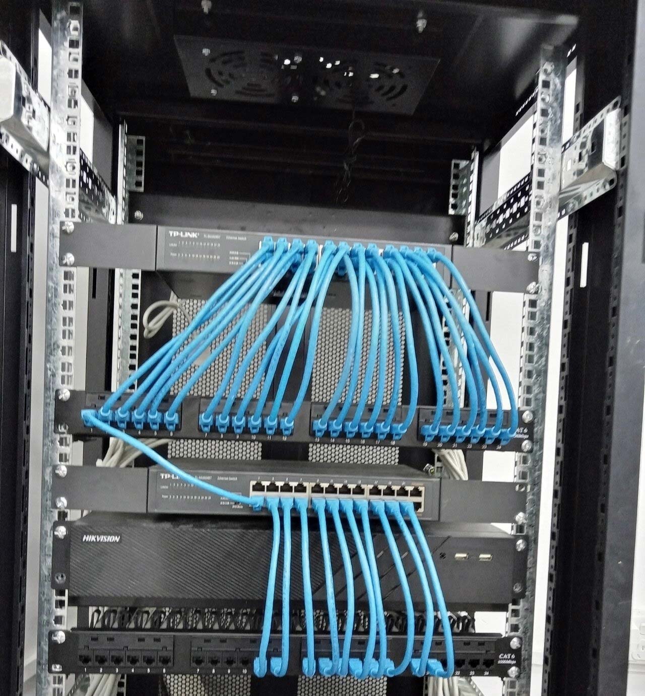
Industrial LAN Cable Application
Where TSN (802.1Qbv/AS) Fits: Hard-Guaranteed Latency for Mixed Traffic on a Single Cable
With IEEE 802.1AS syncing all network devices to within +/- 500 nanoseconds, a time basis has been established across the entire facility. IEEE 802.1Qbv then time-slots control, vision, and IT traffic to prevent collisions and eliminate queues. With the ability to sync, bounded latency is enforced—there are no involuntary spikes that typically cause PLC loops to stall or vision errors where frames are dropped. Once you have TSN-capable network interface cards and switches, one industrial LAN cable can carry isochronous traffic and best-effort traffic without affecting the service.
Why “Microsecond Determinism” is Mission-Critical: The Cost of Jitter and Data Uncertainty
Accurate timing is what distinguishes a smooth production from endless interruptions. Every microsecond of network jitter leads to lost cycles, scrapped parts, unplanned support calls, and time lost without manufacturing. Knowing this cost directs investment in cables and switches to eliminate unreliability or unknown time delays. The examination of an intentional contrast between chaos and planned control helps us better understand the business case.
The Problem: How Video/IT Spikes Cause Motion Control Jitter and Unplanned Micro-Stoppages
In instances where a vision system is processing data, there may be a situation where the PLC loops do not meet a critical deadline. For example, if there is a 5% increase in IT traffic, an increase of 250μs of jitter can be introduced, disrupting a 1 millisecond control cycle, thus leading to emergency stops of the loop. Frame drops in vision systems increase false rejects, sometimes as high as 15%, requiring a manual audit of the product, causing the line to slow and reducing quality throughout. While operating weld robots in a production environment, loss of synchronization can lead to poor overlap of beads and result in an expensive rework situation. The costs associated with these three issues can run up to $50,000 each year for each line in wasted time or materials.
The Solution: TSN’s Time-Sync and Scheduling (802.1Qbv) Hard-Guaranteeing Latency for Coordinated Robotics
IEEE 802.1AS synchronizes all devices to a single clock with ±500 ns accuracy. Every device now has a temporal basis. The network becomes a deterministic fabric. IEEE 802.1Qbv assigns time slots to control, vision, and IT traffic. No collisions, no queuing delays. The laboratories showed TSN reduced the variances in latency from 153 μs to 1.1 μs, keeping PLC loops on specification and vision frames intact. Coordinated robots now can move in sync without the micro-stops that used to halt production. Prioritizing critical traffic on industrial LAN cables allows manufacturers to regain cycles that were lost and dramatically reduce rework costs.
How to Select the Optimal Industrial LAN Cable: A Decision Matrix for 10G Reliability
Selecting a correct industrial LAN cable comes down to factoring both performance needs and environmental demands. A simple decision matrix would weigh the cable type in terms of shielding, connector type, jacket material, and installation conditions. This decision-making approach limits costly trial and error and ensures 10 Gbps throughput in the most important spaces; for instance, end devices. Framing cable selection strategically can turn high-risk failure points into low-risk reliability points. If you want to dive deeper into the distinctions and features of various Ethernet cable categories, the detailed Cat5 vs. Cat5e vs. Cat6 vs. Cat6a vs. Cat7 vs. Cat8 Ethernet cable buying guide will offer valuable insight into selecting the right cable for your application.
Shielding & Layout: The S/FTP vs. F/UTP Choice and Grounding Strategy Near VFDs
Screening cables for individual pairs (at the same-even ratio) but providing overall braided shielding assures 360° electromagnetic interference (EMI) protection. No variable frequency drive (VFD) noise will penetrate the pairs. Foiled/Unshielded Twisted Pair (F/UTP) provides foil protection on a pair-by-pair basis only; thus, overall EMI immunity is very low. Continuity of grounding must be maintained; therefore, bonded connectors and grounded metal trays are necessary for every cable run. If shielding continuity is broken, EMI rejection could go from 100 dB down to 50 dB, sufficient to cause data errors. Testing near high-power motors has shown complete shielding kept 10 Gbps error-free and partial shielding had packet loss over 5% under the same conditions. Proper separation of EMF from trays (and a bonded ground) further isolates the source of EMI.
Connector Showdown: RJ45 (IP20) vs. M12 D-coded (100M) vs. M12 X-coded (10G/IP67) Selection Criteria
RJ45 connectors work well in control cabinets with IP20 and lower costs but lack environmental sealing at the field level. D-coded variants that are commonly available support 100 Mbps data transmission and provide IP67 environmental sealing for low-speed sensors located in a washdown area. Conversely, X-coded versions support 10 Gbps data throughput and provide full Cat6A features, IP67/IP68 environmental sealing, and locking collars that can withstand vibration on field runs. Learn more about the detailed usage and operation of the RJ45 interface in optical modules, which complements the discussion on connector types for industrial environments.
A benchmark for comparison of specifications is indicated below:
- Environmental rating: RJ45 (IP20), D-coded (IP67), X-coded (IP68)
- Speed capability: 1 Gbps (RJ45), 100 Mbps (D-coded), 10 Gbps (X-coded)
- Vibration resistance: 30 g (RJ45), 50 g (D-coded), 75 g (X-coded)
- Cost per meter: low – RJ45, medium – D-coded, high – X-coded
Whether the requirements are guided by budgetary limitations or performance specifications will help specify the best option for the connector. X-coded connections make the most economic sense when evaluating whether there are requirements for washdown or speed.
Comprehensive Cabling for Industrial LAN Cables
Environment & Duty Cycle: Picking PVC, PUR, FRNC by IP Rating, Oil Resistance, and Flex/Torsion Specs
While PVC jackets are acceptable for fixed installations, they will not hold up in flex applications. Polyurethane (PUR) connections meant for drag chains offer the best overall service and can withstand five million flex cycles, oils, and other chemical exposures. In confined spaces, flame-retardant non-corrosive (FRNC) compounds provide a fire-safe benefit at the expense of cable performance, as they do not have a harmful halogen element. It is important to note the operating temperature ranges: PVC (–10°C to 60°C), PUR (–40°C to 80°C), FRNC (–20°C to 70°C). For a comparative analysis on how outdoor and indoor Ethernet cables perform and their suitability for harsh environments, see this informative article on outdoor vs indoor Ethernet cables.
Keep the bend radius ≥8× the cable diameter for static run applications and ≥12× the cable diameter in dynamic motion applications. For continuous-flex applications, select tray-rated cables that are torsion-rated to address the flex, ultimately reducing mid-span failure. Proper material selection minimizes unanticipated breakdowns and extends the lifespan of the cable in harsh industrial settings.
Protocol Impact: Cabling Requirements for PROFINET, EtherNet/IP, and CC-Link IE TSN
Every industry standard has different implications for cable performance and network topology. Selecting the appropriate industrial LAN cables will ensure that real-time classes, isochronous transfers, and network resilience meet protocol requirements. Appropriate cabling will also avoid potential performance mismatch issues and reduce or eliminate impacts to throughput, latency, or degradation of electromagnetic immunity. A further investigation into specific protocols can reveal some fundamental decisions around infrastructure.
PROFINET Cabling Reality: Cat6A for Backbones, M12 in the Field, and Fiber for Noise Islands
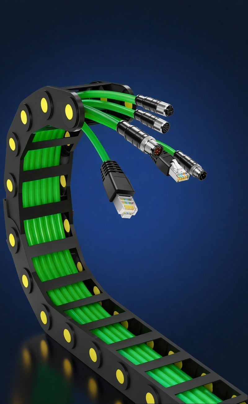
PROFINET RT works on standard Cat5e or Cat6 cables, but IRT mode requires Cat6A for 10 Gbps backbone segments. Field connections utilize heavy-duty connectors which maintain the IP67 sealing in proximity to actuators and sensors. Fiber optic links (e.g., above) effectively isolate noise-prone areas surrounding a toxic high-voltage drive, while preventing crosstalk into adjacent copper segments. This hybrid approach provides the best of both worlds: speed, ruggedness, and electromagnetic interference (EMI) protection with fiber across the many environments of manufacturing.
 EtherNet/IP and Modbus TCP: Ruggedization of Standard Industrial Ethernet Cabling Rules
 EtherNet/IP and Modbus TCP: Ruggedization of Standard Industrial Ethernet Cabling Rules
The Common Industrial Protocol specification for EtherNet/IP supports cabling with a minimum of Cat5e or Cat6, but grounding the shields and the consistent geometry and twist of the working pairs must be considered. Modbus TCP has similar cabling requirements, requiring shielded cabling for the transmitted pairs if in an environment with high electromagnetic interference (EMI). Quality of Service (QoS) tagging is important when using standards-based Ethernet to ensure the integrity of control traffic against bulk data transfers. In fact, as long as the installation is performed correctly, the standard industrial cabling installed should meet the robustness requirements of both protocols.
Why CC-Link IE TSN Simplifies TSN Adoption with Standard Cat5e+ Compliance
CC-Link IE TSN brings seamless time-sensitive networking without forcing users to modify their current cabling setup beyond utilizing a Cat5e+ infrastructure (sockets, connectors, etc.). Engineers can then reuse existing cabling runs of Cat5e+ to reduce capital expenditures and service interruptions due to new installations. More importantly, since it is based on an open standard, CC-Link IE TSN defines standardized TSN profiles that apply to commonly used industrial LAN cable connections. By leveraging existing Cat5e+ infrastructures while having deterministic networking capabilities, users will maximize the return on investment without requiring major cabling investments.
How to Validate Throughput, Jitter, and EMC Resilience On-Site
Hardware implementation in the real world can be different from what is indicated on a datasheet. However, on-site testing shows that industrial LAN cables can meet some of the most challenging throughput, latency, and EM compatibility requirements. A sector-validated process can mitigate potential deployment failures and demonstrate a return on investment (ROI) with cables. A system validating the in-the-field testing eliminates surprises on deployment.
Building the Test Cell: Necessary Equipment for Testing 10Gbps M12 X-coded Under Stress
We advise starting with a TSN-ready switch with built-in support for IEEE 802.1AS/Qbv, which provides time synchronization and temporal traffic scheduling. The next step is to add a traffic generator that replicates mixed control, vision, and bulk IT flows, all at industrial data rates. Add a network analyzer with sufficient accuracy to measure latency and jitter down to nanoseconds. Next, add EMI sources in the form of VFD simulators or portable RF injectors and locate them near cable runs. Lastly, a calibrated cable tester should be used to examine the shield connection to verify continuity and insertion loss. By going through these steps and using the supplied tools, you have now created your own industrial environment, which provides an opportunity to measure EMI weaknesses and their impact on system performance before applying the system in the field.
 How to Measure: Baseline Throughput, End-to-End Latency, and Jitter Under Simulated EMC Noise
 How to Measure: Baseline Throughput, End-to-End Latency, and Jitter Under Simulated EMC Noise
To start, establish baseline throughput by running continuous 10 Gbps traffic for 10 minutes, with acceptable packet loss remaining below 0.1%. Second, record end-to-end latency using the timestamping features in the network analyzer, allowing variance to remain under 1.1 μs. Third, inject EMI pulses at 100 MHz to 1 GHz while repeating the traffic, ensuring jitter remains below 5.4 μs peak to peak. Each test should be run for at least five minutes in order to capture intermittent glitches. Testing data should be standardized in a spreadsheet for comparison across different cable types and installation methods.
Interpreting Failures: Diagnosing Shielding Gaps, Termination Quality, and Incorrect Twist Geometry
In the event of packet loss or high jitter, assess the continuity of shielding on both cable terminations: a broken braided or foil shield provides a dramatic reduction in electromagnetic interference (EMI) rejection. Next, check the quality of the terminations: untwisted pairs longer than 13 mm introduce impedance mismatches. Additionally, if it is possible to measure the twist rate of the cable, compare it against the manufacturer specifications—incorrect twists could ultimately generate reflections and crosstalk. If the issue is minor, try reseating the connectors or re-crimping the terminations. For the remaining cable that exhibited continuous fluctuations in insertion loss, replace those segments of the cable with new cables. Document the failure modes to create a record of the cable that can be used for future cable selections (and possibly installation recommendations). This practical validation process ensures the selected industrial LAN cables function in a deterministic and reliable manner in a demanding manufacturing environment.
The Silent Killers: 5 Common Field Failures and Rapid Prevention Strategies
Hidden cable faults can shut down a production line. Quickly identifying your problems saves you costly downtime. Below are five common failure modes, targeted solutions, and preventative measures to keep your industrial LAN cables operating properly in harsh conditions. Identifying these failure patterns ahead of time saves you thousands in emergency repairs. To expand your understanding of cable faults and actionable diagnostics, explore the in-depth analysis of industrial Ethernet patch cable faults, which offers practical testing and troubleshooting methods.
Wrong Cable for Motion: Using Static-Rated Cable in a Drag Chain → Jacket Cracks and Intermittent Drops
Static cables are not engineered to have the tensile strength and flex lifespan required in drag-chain applications. For example, a PVC jacket may crack after 50,000 cycles and expose conductors. Visual inspections may show cracks longitudinally and intermittent data drops during motion stress. Dynamically rated PUR cables are available, which have 2 million flex cycles tested. Include inspections at every interval of 1,000 operating hours to lessen wear patterns in early stages.
Shielding Gaps: 360° Termination Failures and Why EMC Layout Trumps Spec Sheets in High-Noise Areas
A disconnected braid or foil at connector terminations creates an “EMI leak” and allows noise penetration into the cable configurations. With just one disconnection, what could have achieved shielding effectiveness levels of 100 dB is now capable of only 50 dB, which, next to variable frequency drives, continues to contribute to corrupted data. Be sure to clamp connectors down over the braid and not just the outer jacket material. Do your best to keep wires routed away from high-voltage panels and ground shields at both ends by bonding them to grounded cable trays.
Low-Frequency Pair Use → Reflections, Mismatch, and Hidden Retries That Slow the Line
Dictating control signals to low-frequency pairs invites mismatched impedances. Allowing pairs to untwist longer at the terminations increases their reflectance, causing hidden packet retries. A symptom witnessed is random bursts of latency spikes and diminished effective throughput. Observe TIA’s twist-rate and termination specifications; using pair identifiers will keep things from being miswired.
Brownfield Migration: A Phased Approach to Upgrading to TSN with Minimal Downtime
Upgrading existing production lines can strike fear in plant managers and maintainers due to lasting downtimes or going over budget. Moving to a phased TSN migration—establishing isolated “islands” for critical machinery—provides real-time value without needing to take the rest of the plant down for changeovers. This approach creates a balance between a good return on investment with no operational interruption. Smart planning surrounding the migration aligns infrastructure challenges and unlocks new competitive advantages.
Phased Strategy: Implementing TSN-Ready Islands for Critical Motion and Vision First
Start by developing a map of your highest-risk systems, such as robotic welding cells or vision inspection lines. Create a couple of small TSN islands clustered around those zones, with TSN-capable switches and Cat6A S/FTP cabling. Once the smaller TSN islands are established, perform pilot testing on the actual production equipment during non-production times. Test time synchronization and your scheduling profiles for each specific pilot location. Simultaneously, measure the relevant metrics of jitter variance, frame drop rates, and cycle adherence while tuning the specific application configuration prior to a larger-scale deployment. This approach is gradual; it also reduces the total cost of ownership for your initial investment and demonstrates utility for TSN quickly, which supports stakeholder buy-in.
Coexistence: Bridging Hard Real-Time Traffic with Legacy Cells and IT Analytics on One Converged Network
Implement VLANs or TSN streams to separate real-time control from bulk data on the same physical cables. Implement protocol gateways when existing PLCs cannot use TSN, reconciling CIP or PROFINET traffic into scheduled streams. Monitor utilization: motion and vision data packets receive priority over analytics during peak cycles. All available bandwidth should be utilized for IT tasks until peak cycle performance is adequate; then the leftover will be used for IT. Gradually increase TSN on each island and ensure that each extension functions correctly with legacy cells while moving from cell to cell. This model will reduce downtime and provide an ROI in each phase of a migration.
Single Pair Ethernet (SPE): What Changes at the Edge—and Why It’s Not a Backbone Solution
When it comes to simple sensor and actuator links, SPE has a distinct advantage. Since SPE uses a single twisted pair to carry data along with power, it is able to achieve a maximum of 10 Mbps. This small cable profile significantly reduces the bulk associated with wiring impaired devices, like temperature probes or flow meters, that can be distributed across a facility. That said, SPE is only viable for applications with limited bandwidth requirements for simple applications. For high-speed motion control applications or vision traffic, to remain reliable and effective, we cannot experience the same limitations of relying on SPE as we are already experiencing. In other applications, backbone networks are not going away, but they still need solutions that can sustain viable rates (1–10 Gbps) and maintain EMI immunity at the same time. As the industrial SPE ecosystem matures, with more reliable industrial-grade shielding, higher data rates, and longer reach becoming available, traditional industrial LAN cables based on Cat6A remain the mainstay of deterministic smart manufacturing.
 Cutting Micro-Stoppages and Jitter on a Vision-Guided Robot Cell
 Cutting Micro-Stoppages and Jitter on a Vision-Guided Robot Cell
A high-speed machine vision cell was suffering random stoppages with inconsistent weld quality. Office-grade cables were running parallel to VFDs and were the source of several cycles of jitter or latency up to 210μs—more time than the PLC cycle of 1 ms. The frame drop rate was 12%, causing manual inspections and an 18% decrease in throughput. To fix this issue, a completely shielded installation with 360° coverage was installed, replacing the office-grade runs. Ruggedized connectors with IP67 sealing were used at each junction of the robot and camera. TSN-capable switches were configured using the IEEE 802.1AS (time sync) and 802.1Qbv (scheduling profiles) traffic for both the control and vision traffic. Installers bonded all shields to grounded trays and verified terminations and cable integrity using a network analyzer.
After the upgrades, the amount of jitter fell from 210μs to 1.3μs, allowing PLC loops to remain within tolerance. The frame drops for the vision system were below 1%, reducing false rejects by 30%. Unplanned downtime fell by 65%, allowing for an ROI payback of just three months. Maintenance calls for the network issues were reduced by 80%, allowing a shift in engineers’ time for process improvement. This case study demonstrates how targeted upgrades to the LAN cables, connectors, and incorporation of TSN could produce a significant reduction in micro-stoppages with measurable gains in machine vision and robotics cells. Through advances in robust Cat6A cable construction, reliable sealed connectors, and deterministic networking, operators can prevent jitter-induced failures and maximize uptime.
Your Fast-Track Steps to an 80% Benefit in the Next 30 Days
- Monitor real-time flows: Determine the top five control and vision data streams; label the criticality of the traffic streams.
- Standardize cabling: Eliminate mixed cable runs and replace cables with Cat6A S/FTP and ruggedized field cables for reliable performance.
- Demonstrate TSN island: Designate one line with TSN-capable switches employing IEEE 802.1AS/Qbv; define time slots for control and vision streams.
- Measure metrics: Pending the jitter (baseline and post-pilot [target <5μs]), latency variance (<1.1μs), and packet loss (<0.1%).
- Scale BOM: Determine a repeatable parts list and guide for installation across multiple lines.
- Review weekly: Review test data, modify and test ground/terminations, and finalize deployment plans plant-wide.