Industrial Ethernet Patch Cable Faults: Quick Fixes for On-Site Stability
Industrial Ethernet patch cables are the primary conduits that support communications for industrial networks. Unfortunately, cables are often exposed to conditions resulting in problems that can severely affect production. Discover how industrial Ethernet cables support reliable, high-speed big data transmission in modern networks by reading how industrial Ethernet cables support high-speed big data transmission. If an engineer can quickly and accurately assess maintenance problems in an industrial network on site, unnecessary downtime is prevented, and consequently, expensive downtime can be avoided. When an engineer can quickly diagnose a fault, while not an emergency, reliability can be maintained with a control system for long-term outages. This complete guide emphasizes practical solutions to the most common cable problems, which include physical breakages, signal noise, and oxidized connections. The most urgent challenge emphasized in the guide is fast detection, taking action, and restoring stability to the network.
Troubleshooting is similar to triage in the medical profession — the more urgent signals identified earlier, the more direct remedy may be applied to save the overall network health. Right after diagnosis, field engineers utilizing only the right methods and tools for repair will increase efficiency and eliminate waiting. In this resource, there is simple, straightforward step-by-step guidance and a service tool set to help professionals broaden their technical knowledge to increase speed of repair and reliability of the network.
3-Minute Triage – How to Differentiate Physical Damage, Signal Interference, and Connector Oxidation
The swift and precise differentiation of faults will help you target your troubleshooting of a patch cable. To begin, have a close look at the LED lights on the pertinent network ports. The presence of a green light as a constant is typically an indication of a good link, while a flashing or dim light usually indicates an intermittent link that is most likely a cable fault or connector corrosion. You can amplify this visual inspection by carefully shaking or bending the cable around the connectors while watching the status of the LED. Any irregularities in the LED status during movement of the cable indicate a strong case for physical damage, likely a line break or a loose connector.
It is equally important to distinguish between cable faults and port faults. If the LED is only impacted when you manipulate the cable, your focus should be on the cable assembly. If the LED is flickering at all times, regardless of manipulating the cable, you should be investigating the port or fault at the device. Combining a tactile inspection with your visual inspection of the LED is a simple but valuable method for early fault identification and cable triage that site engineers rely on when working under difficult working conditions.
 How to Pinpoint Hidden Physical Damage Using TDR and Signature Analysis
 How to Pinpoint Hidden Physical Damage Using TDR and Signature Analysis
Relying only on visual inspections frequently overlooks nuanced cable damage that could be deemed negligent. A time domain reflectometer (TDR) emits a diagnostic signal down the cable to identify the return reflections (echoes) that arise from micro-cracks, kinks, or sharp bends. This process illustrates how the system mimics sonar identifying location and obstacles under water. In addition, portable TDR units provide an easy way to test on-site, immediately producing the waveforms with spikes or dips that indicate compromised sections of cable. These types of faults, which can evolve over time, create significant signal degradation that ultimately interrupts performance.
Keep in mind TDR devices cannot identify insulation compression or chemical damage with nonmetallic faults. However, the nearest-end (NEXT) and far-end crosstalk (FEXT) measurements on twisted pairs allow for an added layer of verification. Additionally, if you observe a spike or sudden change in crosstalk signal, that may indicate signal deformation or issues at the connectors. Remember, bending the cable beyond the manufacturer’s specification, which can increase the degree of reflection and return loss, is a consideration when testing to maintain data integrity. To ascertain between smooth bends from cable stress, return loss analysis (RLA) can assist. TDR provides multidimensional measurement opportunities, when supported with NEXT/FEXT, enabling technicians to reveal hidden physical damage and then accurately locate for repairs to avoid subsequent downtime from the repair.
Expanded Operational Steps
- Utilize caution while meticulously calibrating the TDR unit before probing.
- Scan the length of each entire cable span and document all points of reflection.
- Next, combine return loss graphs subsequent to ALL measurements of known repaired cable.
- Deploy a crosstalk tester to determine interference at both the near-end and far-end.
- Finally, determine if the damage requires only a repair or new cable.
The overall assessment and review allows for subsequent maintenance of a more proactive nature, while being simultaneously defined for the overall health of the cable.
Detecting a Micro-Bend Crack in a Cat6 Patch Cable with TDR
A routine check has identified several instances of network failures that were determined to be associated with a Cat6 patch cable. The engineer employed a handheld time domain reflectometer (TDR) to assess the condition of the patch cable. Our testing indicated a considerable peak located about 12 meters into the patch cable. This micro-bend crack was “not visible to the naked eye”. This minor fault initiated internal impedance mismatches that resulted in unstable connections while the system was in operation. After confirming the parameters related to the location of the cable failure, the engineer was able to change that part of the cable easily. This successfully provides an excellent example of how to combine both TDR signature analysis and the skilled use of a tool to help diagnose and repair a hidden physical cable failure, having previously assured network stability. To deepen your knowledge of Ethernet cable capabilities, explore our comprehensive guide to Cat5 through Cat8 Ethernet cables.
 How to Rapidly Diagnose Noise: Differentiating EMI, RFI, and Internal Crosstalk on Patch Cables
 How to Rapidly Diagnose Noise: Differentiating EMI, RFI, and Internal Crosstalk on Patch Cables
Electromagnetic Interference (EMI) has the potential to interrupt communication using industrial Ethernet patch cables, resulting in an unreliable connection due to poor data quality. One of the first things to understand is the difference between electromagnetic interference (EMI), radio-frequency interference (RFI), and internal crosstalk. Understandably, narrowing the troubleshooting process down to these types of disturbances can significantly reduce the scope of the issue. The first step in the diagnostic process is to look at the metrics reported by the device. Metrics such as CRC errors and network jitter are a great starting point. If the device shows a spike in either of these metrics, the cause of the issue may not lie with the hardware, but rather EMI. On top of this, if you are able to record these metrics over the course of days, it will help illustrate the patterns of noise that occur over time, in relationship to environmental factors.
In the field, use a multimeter to make measurements of the continuity of the shielding and contact impedance using a four-probe method. Low resistance readings with a multimeter (<1 ohm) suggest that the connector and shielding are properly grounded. Higher resistance readings (>1 ohm) indicate a fault of some sort with the shielding that is allowing EMI to saturate the signal and interrupt the communication. During the datacomm diagnostic process, after you determine that the EMI issue is not coming from the patch cable, you would identify internal pair interference (or crosstalk) that is typically caused by damage to the cable or improper termination of the pairs. This can easily be verified using the crosstalk measurement reported by the cable analyzer, such as near-end crosstalk (NEXT) and far-end crosstalk (FEXT).
The outline of the process will look like this:
- Continuously check for CRC and jitter data and correlate with measured spikes in noise.
- Verify shield continuity from the connector to the switch port.
- Take a measurement of the grounding resistance and compare it to the planned standards.
- Test for crosstalk and look for pair signal interference.
- After identifying a fault, move the cables or replace the internal shielding.
Overall, a mixture of these steps creates a concise and cost-effective strategy to identify EMI interference without extensive use of spectral instruments.
Isolating EMI Effects Caused by a Nearby Motor in a Production Line
An engineer discovered a repeatable packet loss on a patch cable near some heavy motors. The sporadic CRC errors suggested a possibility of EMI interference. By logically moving the cable further away from the motor, the CRC errors and jitter rapidly decreased. Then, the engineer measured the shield’s resistance with a multimeter and found high contact resistance, which suggested some degradation of the conductive shield. Shielding cables were obtained, and the rerouting of cables fixed the EMI effects altogether. This example highlights the importance of practical error monitoring, verifying the integrity of the shield, and good cable management in EMI solutions.
Quick Fixes for Connector Oxidation: Chemical Cleaning and Field Performance Recovery
Oxidation of connectors is frequently the underlying issue caused by intermittent patch cable faults when using industrial Ethernet. Exposure to moisture and corrosives results in sulfide or chloride-contaminated layers of oxidation that degrade the quality of contact. An effective method for cleaning the surface is with isopropyl alcohol or a solvent specifically designated as an electronic contact cleaner, that will dissolve oxide films without leaving residues and dry quickly, adding no additional moisture. To understand the different Ethernet cable types and their roles in networking, review the insightful comparison of patch cable vs crossover cable distinctions.
If other debris is present, use soft brushes, swabs, or lint-free cloths to remove it first. After treatment, allow the connectors to dry thoroughly to prevent further corrosion. Effects of oxidation worsen with temperature exposure. For example, connectors may work fine while it is cooler, but after a time in heat, the connectors will fail and produce varying faults. The application of a corrosion inhibitor or protective spray can help prolong the life of the connector in harsh conditions. Basic cleaning of the connectors periodically, based on site conditions, can help reduce repair costs and instability in the network. For a comprehensive understanding of how environmental factors impact cable choice and performance, see our detailed guide on outdoor vs indoor Ethernet cable differences.
 How Temperature and Humidity Affect Oxidation-Related Intermittent Failures
 How Temperature and Humidity Affect Oxidation-Related Intermittent Failures
The thermal expansion cycles alter the thickness of oxidation layers, resulting in variability in the electrical contact resistance. The microvariation leads to inconsistent connections and, eventually, network disruptions when contacts fail due to mechanical distress either in operation or through exposure to temperature and humidity conditions. Humidity enhances corrosion by allowing water to accumulate at the contact surfaces, which also increases contact resistance and further deteriorates the electrical connection. Think of the connector surfaces over time as a puzzle piece whose edges were bent from heat/cooling and the addition of moisture, slightly misaligned and ultimately breaking down contacts and the signal path. It is easy to understand why failure is exacerbated in hot and humid conditions. Managing the environment and maintaining connections by cleaning the connectors will assist your industrial Ethernet patch cable network performance despite changing environmental conditions.
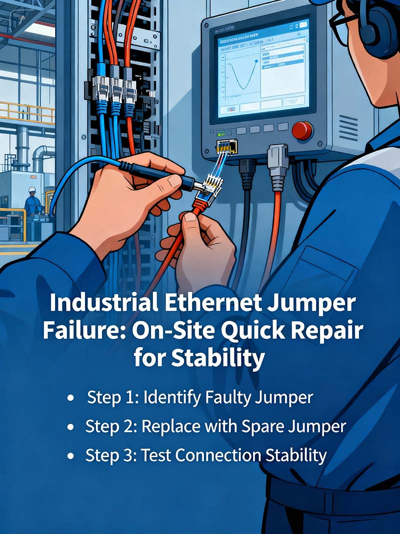
The 5-Step Golden Rule for Fast On-Site Patch Cable Fault Isolation
In order to effectively isolate faults with patch cables, time is of the essence and an actionable decision flow should be known.
- Step 1: Observe LED Status
Lights can be observed as being on, blinking or out. When blinking or out, the suspicion is likely on cable or connectors as opposed to the network device. - Step 2: Review Network Data
Review the CRC, jitter, or packet loss to analyze the possibility of a fault. There are likely patterns of errors or measurable values where cable degradation could be noted or interference may be occurring. - Step 3: Replace with Spare Cable
Replace suspect cables with confirmed spare cables to check if errors go away. - Step 4: Port Loopback
Port loopback will also isolate cable faults by attaching the signal output directly to the input to check that faults don’t persist when isolated from the adjacent device. - Step 5: Mechanical Replication
Try to simulate the change in circumstances (bend cable, shake cable, etc.). Mechanical replication can reproduce faults and verify the cables in the final repair.
This detailed process is around 5 minutes in length and contains visual cues, data metrics, practical testing, and verification steps. This process allows engineers to isolate industrial Ethernet patch cable faults in rapid fashion and confirm quickly.
Choosing and Installing Patch Cables to Maximize Lifespan in Harsh Environments
One needed consideration of environmental severity when determining resilient patch cable will be the MICE classification, which guides the user in selecting appropriate cables for mechanical, ingress, climate, and electromagnetic stresses. During installation, the proper installation techniques used to provide stress relief can prevent micro-damages. Adhering to the proper bend radius, corrugated relief, for example, strain and flexing induced from inserting a cable clip for a bend radius. Avoid creating any tight loops in the cable; without relieving the installed bending diameter cables, there is a risk of damaging or disrupting the cable.
Avoid tight bundles. It is also good practice to avoid mounting or strapping cables too tightly together; a tight bundle also prevents heat from escaping and creates mechanical pressure. Use a cable clamp judiciously and allow natural spacing of cables for additional flex and cooling. Installation considerations may not seem like relevant determinants of system fault or low maintenance issues, but thoughtfulness during installation will mitigate longer-term problems and maintenance challenges, all of which provide durability in an environment that can stress at an accelerated pace.
Installation basics:
- Choose cables rated to site-specific MICE conditions.
- Ensure all bends are kept to the minimum recommended radius or bend radius corrugated relief.
- Fasten without tight bundling.
- Ensure that connectors are all tension-relieved at terminations in the box.
Applying the essentials will contribute to a more reliable network infrastructure with patch cables that will last. For applications requiring higher speeds or long-distance transmission, learn about multimode fiber optic cable types and their uses.
How to Master Shielding and Grounding Verification On-Site for Patch Cable Integrity
The cable shield & ground protect against electromagnetic noise affecting stable industrial Ethernet links for applications. Using a multimeter, resistance can be measured at the cable shield to an electrical earth reference. Values below 1 ohm usually provide adequate reference to earth and are required to block interference. Ensure full shield continuity through the entire length of any patch cable to locate breaks or loose connections that will not allow the shield to work as intended.
Use an oscilloscope—in simple scope mode—over the shield wire to locate intermittent noise or micro-arcing occurring along the shield line. Using an oscilloscope also allows isolating noise not visible with a quality resistance test of the shield. Visualize what happens along the patch cable between the shield & ground to better understand the use of an effective shield. The shield can be visualized as a fortress wall. Any breaks in the wall allow potential damaging outside interference to penetrate the wall into the protected patch cable inside the fort. Regular verification of the shielding and grounding prevents allowing electrical noise to enter the network that, without monitoring, could cause unexpected fault occurrences.
Procedural checklist:
- Measure ground resistance with a multimeter.
- Verify shield continuity over the length of the cable.
- Review oscilloscope tactical waveforms for shield ground interference.
- Repair shielding defects immediately.
By verifying these on-site tests, the technical staff will protect each patch cable and ensure network reliability—even under poor environmental conditions.
Resolving Intermittent High Jitter Fault from Thermal Expansion and Connector Oxidation
 Resolving Intermittent High Jitter Fault from Thermal Expansion and Connector Oxidation
A manufacturing facility noticed intermittent high jitter and packet loss on critical industrial Ethernet connections. The focus of the investigation was a suspected bad patch cable. The problems became worse as the temperature increased during the warmer parts of the day, indicating sweeping physical damage might have a thermal effect.
The methodical analysis included:
- Analyzing network logs and identifying periods of jitter that correlated with increased ambient temperature.
- Observing that there was subtle oxidation on a connector during visual inspection.
- Performing electrical measurements that indicated contact resistance increasing with temperature.
The cable was replaced with a corrosion-resistant material, and the cabling was routed away from heat sources. All the faults disappeared immediately.
Key considerations:
- Any environmental factors, including temperature, may need to be considered when diagnosing the root cause of an intermittent fault.
- Suspected oxidation as possibly the ultimate cause of intermittency.
- Incremental methods of fault isolation together with environmental observations to arrive at a repair solution.
This case exemplifies the intersection between engineering and proper environmental considerations to ensure a resilient industrial Ethernet network.
Selecting the Best Handheld Tester for Industrial Ethernet Patch Cables
The type of tool you select will have a dramatic impact on troubleshooting efficiency. Use handheld testers in the field that have integrated TDR capabilities for accurate troubleshooting. When it comes to industrial/data center installations, testing Power over Ethernet (PoE) cabling is critical. This deals with providing power to devices as well as the data signal. If this is not tested, you can have an issue with powered devices operationally due to defective cabling. Next, usability is essential. Having a simple user interface will reduce the time necessary to train a technician before being able to troubleshoot an Ethernet patch cable defect in the field. However, the less expensive models often lack the necessary features useful for a technician.
Important selection criteria for testing cables:
- Resolution and accuracy of the TDR function
- Testing Power over Ethernet (PoE) load testing
- Ability to operate the tool easily for quick field use
- Cost-effectiveness (paying for features but not features you don’t need)
The use of the right tools enables technicians to accurately troubleshoot defective patch cables very quickly, ensuring that industrial networks are stable and efficient.
When to Replace Patch Cables: Objective Key Performance Indicators from IEEE Standards
The decision to replace industrial Ethernet patch cables should be determined based on documented metrics of the patch cable’s performance, and not based on guessing or subjective evaluation. Critical metrics include attenuation, near-end (NEXT) and far-end crosstalk (FEXT), and return loss as defined in IEEE specifications. Exceeding attenuation limits will reduce the strength of the signal sent through the cable, which can lead to a loss of data integrity for the system. Exceeding the limits for NEXT or FEXT indicates less reliable signals and internal interference ultimately damaging the clarity of the signal. A high reflected power shown with a return loss test indicates a physical fault which in turn may be exposing the system to maximum power loss or signal clarity.
As operators and engineers continually monitor these parameters, no longer will one be utilizing subjective judgment when deciding to replace a patch cable, but instead be able to use verifiable information to determine replacement. When replacement is based on IEEE parameters, it can elevate maintenance and safe operation to levels of evidence-based practice, which can extend the reliability and life of your network.
How to Use Network Monitoring Alerts to Indirectly Identify Patch Cable Problems
Network monitoring systems report rising counts of CRC errors, packet loss, and retransmissions, indicating potential failure of patch cables. Use the timestamp and the ports affected by the alarms to find likely timeframes to investigate patch cable candidates. Defining thresholds for CRC alarms allows you to take action before the fault escalates to errors, dropped packets, and retransmissions. Monitoring error trends provides insight into temporary memory glitches versus chronic patch cable faults. Analyzing the patched cables’ alarm data in conjunction with hands-on analysis of the cable will directly improve the efficiency of the patch cable fault identification process and will aid in repairing faulty patch cables in a timely manner to keep the health of the industrial network intact.