Industrial Ethernet Cables: How They Support High-Speed Big Data Transmission

When it comes to high-speed, reliable data transfer in an industrial environment, it is paramount to have a functioning system for high-speed data transfer as updated operations and automation depend on it. Industrial Ethernet cables perform the important function of transmitting high volumes of data at high speeds and with reliable security features found in harsh environments. A detailed review of the construction of the cables, the limits of performance, and the inherent challenges of application will provide readers with a perspective on making a knowledgeable choice on cables that will provide uninterrupted big data transmission and reliability. This contributes to your industrial successes with an optimized communication infrastructure.
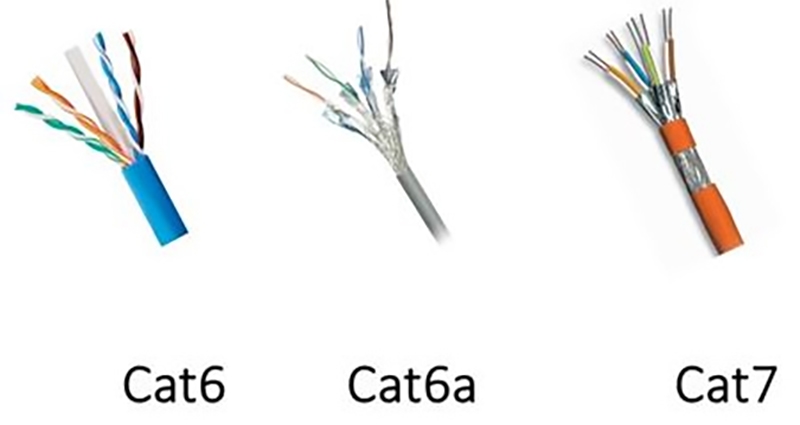
What Are the Physical Bottlenecks in Industrial Big Data Transmission? Quantifying Cat6A, Cat7, and Cat8 Cable Distance and Speed Limits
High-frequency signal transmission is limited in many useful transmission distances by physical phenomena in the industrial environment. Copper-based Cat6A cables can transmit 10 gigabits per second (Gbps) speed and distance up to 100 meters under ideal conditions! The real world is not always ideal, including temperature, which usually decreases the actual transmission distance. Industrial ambient high temperature, around 60°C, derates Cat6A cable performance by about 15-20% of its ideal specifications, which reduces the effective transmission distance to about 80-85 meters.
Cat8’s alternate approach pushes the bandwidth to 2 GHz, supporting speeds up to 40 Gbps, but again only supporting much shorter distances, typically a standard distance of 30 meters because of increased signal attenuation at high transmission frequencies. (Like Cat6A cable, a similar derating by ambient high temperature occurs, typically about 20-25% of the range in high heat environments, which reduces the safe, effective distance [aka transmission distance] to about 22-24 meters).
The increased resistive losses and skin effect are the principal attenuation issues, both of which increase as frequency increases, causing the signal to eventually weaken more rapidly over longer distances of copper pairs. Shielding provides protection against EMI but cannot recover from the distance lost as a result of the fundamental attenuation by frequency. Therefore, engineers will need to balance the speed required with a suitable distance for transmission and the ambient temperature condition. Data centers typically utilize Cat8 to reach ultra-high-speed demands in safe, short-circuit wiring. Cat6A is typically the recommended cable in industrial situations where a longer run for the cord is required, while still being capable of 10G speeds in specifications.
It is important to understand the temperature effect on overall cable transmission distance and specification speed limits of industrial cabling systems to understand if the network design will become unrealistic to the attributes of the operational assets. If temperature limits become excessive, costly future signal degradation of the cable infrastructure can result in data errors.
 How Can Hidden Killers Like Skin Effect, Pair Imbalance, and Crosstalk Be Engineered Out in High-Frequency Cables?
 How Can Hidden Killers Like Skin Effect, Pair Imbalance, and Crosstalk Be Engineered Out in High-Frequency Cables?
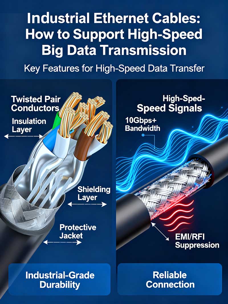
High-frequency industrial Ethernet cables experience three primary foes of signal integrity: skin effect, pair imbalance, and crosstalk. All of these phenomena negatively affect the quality of the data being transmitted through the Ethernet cable by either diminishing the strength of the signal or causing interference. These points where signals may lose integrity most often become problematic when demanding faster transmission speeds. Skin effect forces alternating current to flow at the outer surface of the conductor, thus increasing the value of the effective resistance as frequencies increase. Therefore, signal attenuation occurs when the distance between the transmitting point and receiving point is too significantly long, similar to when there is congestion caused by the ordinary width of a two-lane road; basically, the vehicles are slowed down when flowing through the areas of congested road.
Cable designers address skin effect by designing cables with precision twisted pairs. Tightly and uniformly twisted pairs of conductors use electromagnetic fields to balance the forces that cause each conductor to imbalance. Think of the conductors twisting tightly as a synchronization between dancers, minimizing unnecessary disruptions while still flowing in the same direction. An innovation of structural design in Cat8 cables is the T-Bar (cross-core) design, which positions a small plastic spine between the four twisted pairs. This T-bar serves two purposes: greatly reducing crosstalk by physically separating the affected conductor pairs, and additionally stabilizing the geometry of the cable, thus maintaining spacing and impedance between pairs of conductors while transmitting at high frequency.
Important when getting into the world of high frequencies, impedance stability is paramount because fluctuations would cause a signal to reflect and therefore lose strength, similar to when bumps in the road cause vehicles to jolt along the road, slowing their speed. The benefit of crosstalk mitigation, as an added benefit of the T-bar design, minimizes—almost to the point of exclusion—data corruption, as these brackets normally exist between adjacent pairs to stop interference. Combined with additional shielding layers, the added benefit is to ensure a good connection with very low or reduced noise even at 2 GHz.
In summary, industrial Ethernet cables are carefully designed with engineered pair twisting and T-Bar cross cores to eliminate the invisible foes of signal integrity while honing in on their primary purpose of being a reliable pathway for high-speed big data.
Why Does Protocol-Cable Precision Matter? Quantifying Jitter and Latency Requirements for EtherCAT and TSN Networks
Timing accuracy in industrial networks is vital to the success of big data transfer. Network protocols such as EtherCAT and Time-Sensitive Networking (TSN) depend on having extremely low jitter and latency—often measured in nanoseconds. Adding just a little bit of delay or jitter will break synchronization, resulting in either data loss or loss of operation. To satisfy TSN cable specifications, as well as EtherCAT latency requirements, engineers must perform accurate link budget calculations. Engineers measure the total delay budget per cable length, switches, connectors, and endpoints to guarantee timings remain within the protocol’s jitter tolerance.
Jitter tolerance is defined as the maximum deviation from the expected arrival time of the frame that the network can sustain without losing any information. For example, TSN can have jitter tolerance of tens of nanoseconds, and therefore cables must exhibit the least amount of delay. As an example, EtherCAT networks require ±20 ns precision timing. This is accomplished by methods such as distributed clock schemes. TSN protocols increase timing precision by the IEEE 802.1AS standard in order to time synchronize, and IEEE 802.1Qbv adds scheduling to facilitate packets being placed on the wire with strict timing.
To calculate the link budget, total propagation delay per cable meter (which is cable-dependent and temperature-dependent), switch processing delays, and all internal latencies must be summed. An example would be a Cat6A cable, which has about 5 ns/m of delay; Cat8 can slightly improve or lower delay with advanced internal materials and designs. Ultimately, good network design will utilize the allowable jitter and the allowable delay and balance these against cable length to satisfy the protocol. If a cable cannot meet low delay and low jitter, it will inflate the jitter budget and force either shorter cable runs or use of more expensive ports. Visualizing the delay budget is like being a tightrope walker. The cable and network cannot allow the timing of communication to slip beyond a narrow band or threshold. Ensuring its timing precision will enable data to flow seamlessly to support industrial automation, robotics, and high-speed control applications.
To sum up, precision between the protocol and the cables is essential to meeting the timing specifications of EtherCAT and TSN. Knowing and applying jitter tolerance and link budget concepts facilitates network engineers in selecting and deploying industrial Ethernet cables that will achieve ultra-low latency while maintaining reliable big data transmission.
 How to Decide Between 10G/40G Copper Industrial Cables and Multimode Fiber? Performance, Cost, and Distance Trade-offs
 How to Decide Between 10G/40G Copper Industrial Cables and Multimode Fiber? Performance, Cost, and Distance Trade-offs
When choosing between copper industrial cables (10G/40G) and multimode fiber, you must consider your needs for performance and operational limitations. Copper, such as Cat8, is exceptional for short distances and high speeds, being able to receive a reliable signal up to 30 meters with minimal interference. Fiber optics, on the other hand, offer great distance—it can be hundreds of meters—without electromagnetic interference and is therefore ideal for a backbone. When a consumer considers the value of copper or fiber, they must also consider that prices are different. Fiber generally costs more upfront, and installation is more complex and, hence, more expensive. Nonetheless, when a consumer anticipates ultra-high bandwidth over a long distance, it is reasonable to expect the cost for expansion of limited bandwidth (to copper). Particularly as MTP/MPO connector pricing decreases, fiber becomes the requisite option for user expansions at a lower cost. Learn the difference between patch cables and crossover cables for proper Ethernet connections. Read more
MPO (Multi-Fiber Push On) and MTP (Mechanical Transfer Pull) play a critical role in deploying fiber into an industrial data center and cabinets. MPO connectors are structured to be high-density and allow for quick, cost-effective cable installations when many fibers are involved. The dramatic change in space requirements and labor makes 24-fiber MPO connections easier to install than many LC duplex connections in a rack. LC duplex is more often used for one-to-one node connections. LC multi-stranded connectors are flexible for short runs, whereas MPO/MTP interfaces allow for fast, cost-effective, and high-density installations while continuously offering scalability without any significant splicing or complexity with terminations. Truly, when a user is expanding or updating a system, this comparison becomes significant.
The costs to install or deploy spliced fiber will vary based on the fiber type and the context of the deployment. If we are considering field-splicing multimode fiber, we are likely considering a fiber with a core diameter, typically 50 or 62.5 microns, as these types of fibers are common in data centers. Field splicing with multimode fiber will involve an exact fusion or mechanical splice, which would certainly add hundreds of dollars to the cost per fusion or splice. Pre-terminated MPO assemblies are likely factory terminated, which would be a more straightforward process as they will not require labor-intensive field splicing. For short, high-capacity runs found in cabinets or data center pipelines, pre-terminated MPO/MTP connectors are often a more reliable solution for installation than splicing in situ. With hundreds of fiber links, this approach decreases both operational costs as well as increases consistency and performance. This type of deployment continues to support in-situ multipurpose splicing, which is efficient, but that deployment structure becomes a more viable option when scaling effort is needed for hundreds of fiber links. Explore OM1, OM2, OM3, OM4, and OM5 multimode fiber types and their industrial applications. Explore more
What Materials and Shielding Ensure Durability in Harsh Industrial Environments? PUR/TPE Jacketing, IP Ratings, and Advanced Shielding Explained
When cables are deployed in tough industrial conditions that include damage from chemicals, extremes of hot or cold temperature, and mechanical strain, it is important that the cable jacketing materials have excellent resistance to mechanical strain, extreme and irregular temperatures, and chemical exposure. Polyurethane (PUR) typically provides much greater resistance to motor oils, cutting fluids, and other industrial chemicals where exposure is likely, which prevents swelling, cracking, and degradation of the jacketing. This results in a longer life for the cable, rather than degradation from prolonged exposure to chemicals.
Thermoplastic elastomer (TPE) jackets are an excellent choice as well; they are incredibly flexible, durable, and can retain their performance when repeatedly bent in tough conditions. PUR-jacketed and TPE-jacketed cables nearly always meet UL certification, which means the jacket is likely to perform better mechanically and in safety tests for durability, etc. IP ratings inform you about the ability of the cable to resist the ingress of dust and to be submerged in water. An industrial Ethernet cable with an IP67 rating or higher indicates that the cable is dust-tight and can be soaked in water without negatively affecting the signal quality or changing the cable’s structural integrity; this is especially needed in tough industrial conditions.
In terms of electrical performance, you can opt for advanced dual-layer shielding, which provides more effective shielding from EMI than a plastic jacket alone. This is usually a combination of foil shielding and braided shielding in one layer, which is particularly important for high-frequency signals used for big data. You want to minimize external noise and crosstalk from EMI, and dual-layer shielding is an effective way to provide flexible shielding without adding stiffness to the cables.
In sum, when there is a risk of exposure to mineral oil and other chemicals, you should select PUR jacketing. TPE provides excellent mechanical strain resistance, and combining these attributes with high IP ratings and dual-layer shielding produces the most advanced cables for fast data transmission applications needed in industrial situations. Understand the differences between outdoor and indoor Ethernet cables for harsh conditions. Learn more.
 How to Best Install High-Frequency Industrial Ethernet Cables? 360° Shield Termination and M12 X-Code Connector Usage
 How to Best Install High-Frequency Industrial Ethernet Cables? 360° Shield Termination and M12 X-Code Connector Usage
When installing high-frequency industrial Ethernet cables, it is critical to pay attention to cable preparation and terminations. Keeping twists intact during the cable termination is the most important consideration because unscrewing twists will cause impedance mismatch, which can lead to high return loss (RL) and degraded signal quality. The lengths of your strips are very important; exposing too much conductor or unscrewing pairs too much will put the cable out of its built-in electromagnetic balance, and this would create reflections and noise, which would be more problematic the faster you go (think gigabit).
A good technique to combat electromagnetic interference is to terminate the entire cable shield uniformly to the termination using the 360-degree shield termination method. A 360-degree shield termination method ensures continuity of shielding coverage through the connection point to eliminate EMI that can corrupt data streams. M12 X-Code connectors are an excellent connector choice for industrial applications needing a reliable termination that can withstand vibration. M12 X-Code connectors are very compact and fully shielded, with IP67 ratings against dust ingress and moisture. M12 X-Code connectors are the X-Code for the size and, at the time, will support up to 10 Gbps and have their own crimping system that prevents jacket torque on the cable, so you can keep the twists inside the cable.
In addition to vibration resistance, M12 X-Code connectors have gold-plated, machined contacts and crimpless shield termination flanges to provide reliable signal transmission over extensive cycles of operation. Many industrial cables offer reliability in performance but are not designed to process the preparation and installation factors. This makes M12 X-Code connectors durable in the design to support good cable preparation practices and can reduce service costs since the cost associated with not having to service cable repairs is lower due to fewer connection failures.
Overall, combining cable preparation, 360° shield termination, and M12 X-Code connectors for a dependable low RL connection will pay off by insulating against EMI and unwanted movement in high-frequency industrial Ethernet cables associated with large amounts of data without data loss and ensuring critical stability whenever there are harsh conditions in the industrial network.
How to Expertly Diagnose Industrial Ethernet Cable Issues? Testing NEXT, ACR-F, and RL with Certifiers On-site
Diagnosing an industrial Ethernet cable fault requires the understanding of three key test parameters: near-end crosstalk (NEXT), attenuation-to-crosstalk ratio far-end (ACR-F) or attenuation-to-extremely crosstalk ratio, and return loss (RL). These parameters indicate the ability of the cable to maintain the integrity of the signal and can help readily identify typical fault areas. NEXT is the measure of crosstalk between two adjacent wire pairs at the termination point on the source side of the cable. Higher NEXT values typically indicate an installation issue, such as bad termination or damaged shielding. For example, when connectors are installed incorrectly, this will lead to a higher mated crosstalk value that will interfere with the flow of data.
ACR-F measures the difference in attenuation and crosstalk at the termination point on the receiving end of the cabling path. A lower ACR-F value indicates that the cable or installation is not adequately isolating from adjacent pairs, which is frequently due to cable degradation or external electromagnetic (EM) interference. RL characterizes the strength of the reflected signal due to an impedance mismatch. High RL is typically associated with physical damage—for example, the cable being bent tighter than the manufacturer’s bend radius, damaged cable, or a connector not fully mated. Reflections can cause ambiguity in cable signals, which will adversely affect the quality of signals and transmission.
On-site cable certifiers allow technicians to run a complete series of tests and data collection to include some or all of the measures mentioned above and any other key measurements. For example, when technicians see that the RL is above a certain dB level, they suspect that a fault needs to be addressed. If they can correlate their results with physical inspection, it allows for a focused review rather than just replacing a cable. Many advanced tools combine several of the test functions and, more importantly, provide a localized fault measurement or identification of potentially faulty cables. Techniques such as Time Domain Reflectometry (TDR) help locate breaks or shorts within meters and aid in repairs.
A useful systematic approach includes the following:
- Conducting a visual inspection to identify observable damage
- Conducting and documenting end-to-end testing with certifiers or another test device, including the connectors
- Reviewing and interpreting the cable measurements with industry parameters for NEXT, ACR-F, and RL
- Making connections between the cable test results and the condition of the physical cable
By using this approach, technicians ensure and maintain the uptime of networks with the confidence that the industrial Ethernet cables are operating within specification, ultimately providing reliable high-speed big data transmission that operates effectively in harsh conditions.
 What Can a Real-World Case Study Teach Us About Optimizing Industrial Cable Installation for Big Data?
 What Can a Real-World Case Study Teach Us About Optimizing Industrial Cable Installation for Big Data?
A manufacturing plant experienced some network slowdowns and packet loss, impacting production efficiency. Upon investigation, it was determined that obsolete cable was the root cause of the performance problems due to the volume of high-speed data required. As part of the manufacturing plant upgrade to support high-speed data, new Cat8 cables with more robust installation methods were employed, which changed the performance of their network from pre-upgrade to post-upgrade. Prior to the upgrade, the throughput of the network topped out at around 1.5 Gbps, with packet loss near 8%. After installing high-quality industrial Ethernet cables and implementing some cable prep techniques properly, such as maintaining the twist in the cable and utilizing advanced shielding, the throughput was pushed to 10 Gbps and the packet loss was now below 0.5%, meaning that there were more reliable data transfers, resulting in fewer communication errors.
While installing the Cat8 cables, the installation used 360-degree shield termination and new M12 X-Code connectors that provided more vibration resistance and return loss mitigation. These benefits helped improve both signal integrity, despite the vibrations that factories normally experience, as well as the challenges related to electromagnetic interference. In addition, the manufacturing plant plans to integrate Single Pair Ethernet (SPE) for their edge sensor deployments to reduce cabling needs. Suppliers of SPE data communication assert that it will simplify the cabling need, as well as allow for direct sensor-to-controller data exchanges with minimal latency, which is ideal for real-time monitoring at the edge of the production line.
This case demonstrates both the significant impact of using the right industrial Ethernet cable and the impact professional installation could have on the performance of a network utilizing big data. The quantifiable differences in speed and reliability reinforce that spending money on higher-quality Ethernet cables can solve the majority of the challenges faced in data communications in an industrial setting without losing sight of future projects that may leverage newer technologies like SPE.
How Do Protocol Evolution and Material Innovation Shape Industrial Ethernet Cable Standards?
As protocols such as Time-Sensitive Networking (TSN) and EtherCAT develop, industrial Ethernet cable standards trend toward tighter control of jitter and latency. The advancement of these types of protocols creates a demand for improved cable designs to produce the lowest delay possible while keeping the signal stable even under extreme real-time limitations. Protocols such as TSN can require jitter tolerances on the order of a few nanoseconds in order to sync up a very complex automation system. Cable certification standards have changed to quantify the precise timing requirements while still noting guidelines for the EtherCAT latency standards required. Therefore, designers are continuously experimenting with conductor geometry, shielding, and other materials.
Material engineering has advanced to support the protocol needs with new jacketing that can withstand temperature variations, chemical exposure, or mechanical forces without reducing electrical performance. Improved shielding strategies have reduced electromagnetic interference to help ensure cables maintain their signal energy and compatibility with the protocol. Cable certification standards have also begun to focus not only on bandwidth and attenuation but on parameters essential to timing accuracy—such as delay skew and return loss under various environmental conditions. This ensures that a protocol-specific cable will operate reliably under TSN and EtherCAT specifications.
In the near future, Single Pair Ethernet (SPE) will become an alternative opportunity offering less conductor wiring for simpler edge sensor networks. The fewer conductors and the fact that it is designed with each protocol in mind make it ideal for the distributed nature of data acquisition with low latency and more straightforward installations. The standards for industrial Ethernet cables will be defined by advancements in protocol and new materials. Manufacturers and designers will continue to develop cables and enhance robustness while also meeting jitter and latency requirements.
Updated protocol and new materials will facilitate this knowledge to be applied in cable choices to ensure no loss of network compatibility and performance in the future.
What Are Future-Proofing Strategies? The Role of Single Pair Ethernet (SPE) and Fiber Optics in Distributed Big Data Networks
Single Pair Ethernet (SPE) is revolutionizing the basic cabling connection by utilizing a single twisted pair rather than traditional four-pair cabling, thereby simplifying the connectedness for edge sensor devices. Having such a minor amount of wiring can deliver real-time data with limited latency, making it ideal for distributed sensing networks. At the same time, fiber optics are continuing to expand their footprint in the context of industrial big data through unmatched bandwidth and immunity to electromagnetic interference, which enables transporting large amounts of data over the long haul.
Ultimately, future-proofing industrial networks integrates a combination of SPE for localized, simplified connections and fiber optic backbones that support high-speed aggregation and processing. This hybrid approach solves the increasing volume of big data, supplemented with an easily scalable and flexible infrastructure. In the end, planning with these technologies will enable industrial Ethernet cables to serve the purposes of data-carrying capacity to meet the evolving demands of the future—an optimal balance between easy deployment, reliable data throughput, and durability to withstand working conditions.