How to Test Fiber Optic Modules: Tools, Procedures & Troubleshooting Explained
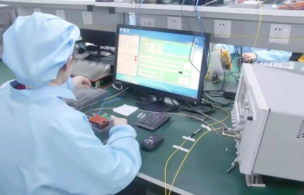
Modules will serve as the foundation of high-speed communication networks; therefore, their reliability is vital. Just a small disparity in performance from the module can interrupt the flow of data, leading to costly network outages. Therefore, testing fiber optic modules will identify hidden flaws and check the module quality, ensuring reliable communication performance.
Properly testing a fiber optic module with the correct diagnostic tools, methods, and properly reading test data was covered in depth in previous sections of the course. You should also be able to apply advanced methods of troubleshooting fiber optic modules in order to troubleshoot issues as quickly as possible to avoid long outages.
Some exclusive case studies and comparisons of tools are also presented as a way to understand more about improving the process of module testing. Ultimately, mastery of fiber optic module testing will support your efforts to keep networks usable and maintain performance regardless of conditions.
This section will clearly lay out a path through critical testing tools and step-by-step procedures to have the best module testing experience, keeping fiber optic networks healthy and reliable.
Why Is Fiber Optic Module Testing Essential for Network Stability?
Fiber optic modules (SFP) or Small Form-factor Pluggable transceivers play a critical part in ensuring fast and stable data flows throughout the network; testing them is like performing a thorough health check on a person. SFP testing can be seen as proactive health testing for the network’s “lifeline.”
Even a minor malfunction or degradation to fiber optic modules can lead to dropped connections, reduced data throughput, or, worse, data outages. You can think of it as regular health checks for vitals, with the goal of catching possible issues before they develop into larger problems.
SFP diagnostic tools, which measure things like optical power, temperatures, voltages, and signal quality, provide insight on module health status by monitoring those key parameters. In some respects, SFP diagnostic tools can be considered digital “guardians” of the network, and are constantly evaluating for faults over and above what is visible during visual inspection.
Acting on potential issues early grants network operators the ability to correct or replace parts before the faults hit a safety net and cascade through the component, with the end goal of maintaining a high-performing network.
Testing SFP modules goes beyond visual inspections. There are a number of types of specialized fiber optic testers that can measure key metrics including signal strength, error rates, and back up all tests for performance under real network or simulated loads.
In this manner, SFP module testing is both methodical and comprehensive, verifying SFP modules meet manufacturer performance specifications and are operating to industry standards and best practices.
As a result of routinely testing SFP modules, both network reliability and troubleshooting diagnostics can improve, making it more targeted and efficient.
Ultimately, regular testing of the fiber optic module serves as the backbone of network stability and helps avoid costly downtime—not to mention the integrity of data flow.
Maintenance of any car or vehicle is essential to keep it operating smoothly, and a network needs precise SFP tests and diagnostics to keep critical communication channels operating without interruption.
The Benefits of Routine SFP Testing:
- Identify hardware degradation or fault early
- Ensure optical signal quality is well within expected ranges
- Reduce the risk of network interruptions
- Increase troubleshooting accuracy and speed
Emphasizing preventive care is vital to sustaining networks at optimal speeds and performance, while also saving time and money over the lifecycle of the module. Building a platform for trusted SFP test routines and diagnostic tools should become an operating strategy for any enterprise with a fiber optic infrastructure.
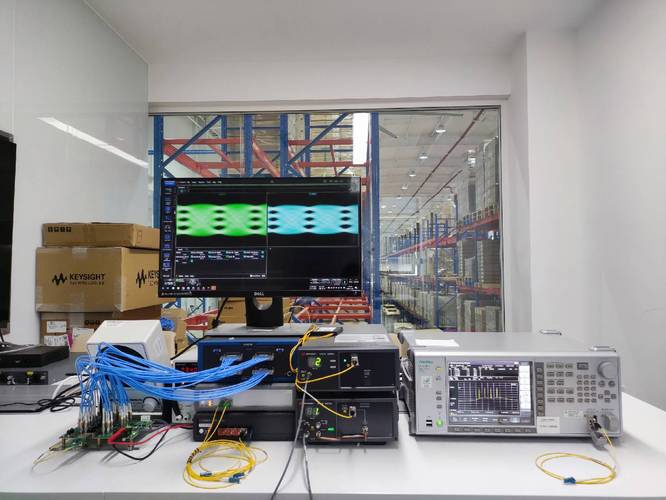
What Are the Five Must-Have Fiber Optic Testing Tools for SFP Test?
To maintain performance and assurance within the network, testing SFP modules requires having the appropriate tools. Just like a mechanic, there are specialized tools for whatever you need to verify the overall optical testing requirements. This set of tools will inherently address everything you need.
- Optical Power Meter (OPM):
The OPM provides a reading of how well the SFP module is transmitting or receiving any light. If the power levels are correct, the module is capable of transmitting signals. Think of it as a gauge that shows evidence of fuel flowing in an engine; that gauge is satisfied with optimal “optical energy” being delivered on the other side without exceeding its threshold. - Optical Time-Domain Reflectometer (OTDR):
An OTDR measures for breaks and is even adept at finding bends, and just like the OPM, it sends pulses of light into the fiber and receives the attenuation levels from the reflections captured in the energy levels coming out of the fiber. In addition to reporting the overall health of the fiber, OTDR measures the distance to the faults or imperfections and will provide an accurate report for the technician to make repairs. In some ways, it functions like sonar that reveals hidden defects between the smooth surface hull of a yacht to the ocean floor along its hull path. - Bit Error Rate Tester (BERT):
A BERT is a tool used to verify that data is being successfully passed through a fiber by sending predetermined test patterns across the fiber and looking for errors. This test is extremely important when establishing the integrity of data to be transmitted in real traffic conditions. You can think of this as a spellcheck in digital communication applications, looking for mistakes that can degrade the quality of the network. - Visual Fault Locator (VFL):
A VFL uses a red laser to emit visible light through the fibers to highlight any breaks or imperfections in the fibers by the light that escapes the fiber. VFLs provide a simple but effective visual way to quickly identify failures in the connection, much like using a flashlight to see cracks in a darkened tunnel. - Digital Diagnostic Monitoring (DDM) Tools:
DDM tools read real-time diagnostic data internally in SFP modules, including things like temperature, laser current, and voltage. This data, all measured in real-time, indicates the condition of the module and is valuable in maintaining a proactive maintenance schedule. The DDM tools act like a fitness tracker for your optical module by monitoring the metrics inside the module.
All three tools discuss a different area of SFP performance, from physical faults to data quality to module health. It is only when the three tools are used together that we have a complete and thorough testing protocol that will allow nothing to slip through the cracks.
In complex fiber networks, we need to assume that the fiber is not going to self-heal, so all of the tools above—the specialized optical testers and optical test equipment—will be important in maintaining stability and reliability in your connectivity.
How to Choose the Right Fiber Optic Tester? Exclusive Comparison of Top Tools
Choosing the appropriate type of fiber optic tester is essential for efficient and effective SFP diagnostics in order to maintain network reliability and accuracy. Think about when you select a car—whether the outcome is how the car performs, how much it costs, or the intended use of the car—it will, in part, always be influential in the selection of any type of vehicle.
Likewise, with fiber optic testers, they will each perform exceptionally well in either one, two, or all three areas based on the testing needs and available budget.
Here is an exclusive comparison of five of the most popular fiber optic testers:
| Tester Model | Key Features | Ideal Use Case | Approximate Price |
| OTDR Fiber Tester | High accuracy, fault location, event mapping | Long-haul network diagnostics | $2000–$8000 |
| Handheld Optical Power Meter | Measures power loss and signal strength | Routine field checks, power verification | $100–$500 |
| Bit Error Rate Tester (BERT) | Data integrity assessment via error rate | Network stress testing | $1000–$3000 |
| Visual Fault Locator | Simple, visible light for fault detection | Quick cable damage identification | $100–$400 |
| Digital Diagnostic Monitoring Tool | Real-time SFP health metrics | Continuous monitoring, preventive maintenance | $500–$2000 |
OTDR testers are extremely precise in locating fiber faults and are excellent for complicated network configurations, but they tend to be expensive and require a fair level of expertise to use properly.
Optical power meters are easy to use and inexpensive. Basic power measurements are usually completed every day to check that the signal is within an acceptable range without being over-saturated, and measurement range thresholds are often included as an integral companion tool.
BERTs work best at determining data transmission fidelity under load. These benchtop or rack-mounted testers are also employed when all optical channels must be stress tested to confirm their overall performance.
VFLs provide a quick and economical visual means to locate fiber breaks or high-loss points within the cable, with the use of a visual indicator at the sending end of the cable while it is connected to the supply, to conveniently match the practical power supply.
DDM tools gather and report key diagnostics internally sent from the SFP modules. They contribute to a more proactive maintenance approach rather than a reactive repair need.
Choosing the best optical-fiber tester for a specific, immediate, or ongoing application is a product of taking stock of the complexity of the networks, budget, and testing requirements. For more thorough diagnostics coverage, many times one will utilize multiple combination tools.
Purchase decisions for optical test equipment can be simplified and assessed, no matter the scale of data center and enterprise networks, by knowing the strengths of each test device.
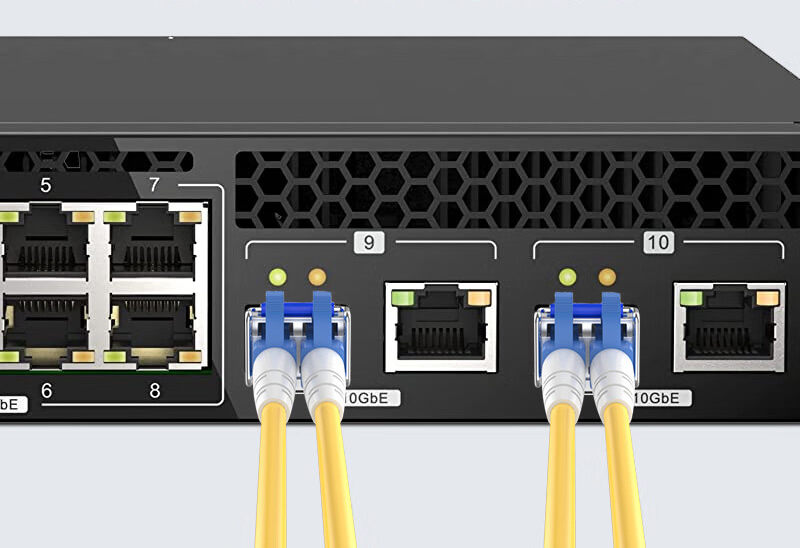
What Are the Step-by-Step Procedures for SFP Module Performance Testing?
When testing an SFP module, there is an organized process to follow as you want to ensure the module performs as expected and is reliable in your network. Think of it as tuning an instrument; each step will allow you to make the necessary adjustments for the SFP module to transmit a signal. Reliably transmitting without issue is about as enjoyable as an out-of-tune violin.
- Visual Inspection and Compatibility:First, visually inspect the SFP module for physical damage as well as dust or bent pins. Cleanliness is vital to performance as dirt will affect the signal. Then verify that the SFP module is compatible with your network equipment via data rates, fiber type, and wavelength specifications.
- Proper Insertion and Link:Insert the SFP module securely into the proper port. Use the device interface to verify the link is present and then that it is recognized. Basic communication has occurred and as a result the SFP module is able to relay basic functionality.
- Optical Power and Signal Quality:Using an optical power meter, measure the optical power output and input. Measure optical power output and the necessary input level (via numbers specified by the manufacturer). We now know we can transmit and receive light signals.
- Data Transmission and Bit Error Rate Testing:Run test data through the SFP and statistically evaluate the error rate using a Bit Error Rate Tester. Low error rates indicate that the SFP module can run real network traffic without data corruption or data loss.
- Link Stability and Stress Testing:Examine the connection under load to check stability by looking for packet loss, latency, and disconnects or intermittent disconnects. Performance will highlight any potential weaknesses of your link that may lead to failure in the future.
- Loopback Testing (if supported):If you have the option for a loopback, enable loopback mode and internally send signals to receive on the same module. Loopback indicates the internal electronics and components are not damaged.
- Documentation & Reporting:If you have input values, errors, and results documented already, then record observed values, errors, and results. If you do not, or you keep minimal documentation during testing, you will eliminate future troubleshooting and related work if you maintain documentation for future reference and quality assurance.
Once these optical tests are performed on the SFP module, you can ensure that it is operationally working as expected. This proactive approach will assist in minimizing downtime and maintaining data reliability. The step-by-step process of performing these optical tests will optimize and reframe any complex testing procedures that may have felt overwhelming earlier into actionable tasks you can complete to keep the system running optimally.
Why Are Optical Power and Bit Error Rate Key Metrics in SFP Testing?
The two main measuring points are optical power (or Tx and Rx power) and BER. Optical power measures transmitted (Tx) and received (Rx) light levels. Tx power indicates how strong the signal is once it exits the transmitter, while Rx power determines how strong the incoming signal is at the receiver.
Both are important to know and stay within defined limits. If Rx power is too low, detection of the incoming signal is poor and the connection may fail. If Tx power is too high, the internal components of the module could be damaged. It is similar to volume levels. If the volume is too low, your ability to obtain the information is problematic. If the volume is too high, the integrity of the information could be compromised.
In terms of data integrity, one of the tests, the BER test, sends known data patterns over the fiber link and counts the errors that it receives. In fiber networks, even a small or ridiculously small increase in errors could be detrimental and cause errors to applications, cause problems for a video stream, drop a call in a voice network, etc.
Low BER values indicate a clean signal and a healthy network. Very importantly, BER testing provides an idea of actual traffic, which aids in contemplating, establishing, and validating that the SFP module can maintain operations with real-world lag in traffic that can manifest faults.
Although optical power and bit error rate tests are different, they combine to form a complete picture of SFP transceiver health:
- Optical power provides confidence that the physical signal (optical energy) is strong and safe.
- BER gives confidence that the data traveling through optical energy is accurate.
A regular schedule for optical power and bit error rate testing provides the best chance of catching those subtle issues early on, like a dirty connector, an improper fiber bend, or in the case that the laser is failing, before the faults can fully develop, leading to degradation of networks, downtime, urgent repair processes, and costly repairs.
When the optical power and BER rates are regularly tested, fiber optic networks are more efficient, reliable, and can support the demanding data needs we rely on!
Key Points:
- Proper Tx/Rx optical power ranges ensure stable operation and that the signal will not be damaged.
- Low BER values indicate the data is being transmitted accurately and is of high quality.
- A combined approach to optical power and BER testing provides the basis to effectively evaluate the performance of an SFP module.
If nothing else, at the very least, understanding these metrics is imperative to the maintenance of strong and resilient fiber optic communication links!
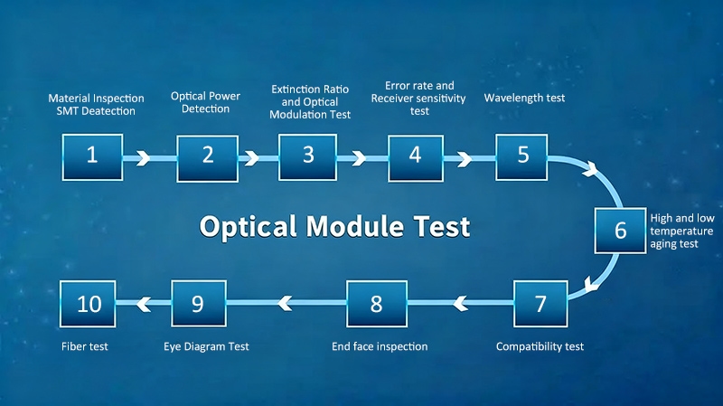
How to Diagnose SFP Module Issues Using Diagnostic Data?
The process of diagnosing problems with an SFP module begins by looking at the most important diagnostic values, such as temperature, voltage, and laser power. These values serve as vital signs since they tell you the underlying health of the module and help to identify potential problems before they negatively impact the performance of the network.
Monitoring the temperature of an SFP module is critical to the performance of the device. High temperatures can often bring about instability of the module and significantly shorten its lifespan. If the temperature frequently spikes, it may point to inadequate ventilation or other components starting to fail. The thought process here is quite similar to an engine overheating.
It is important to observe any temperature readings, as temperatures that are too high could indicate that something is starting to fail and could eventually result in damage, just like an overheated engine can become damaged. Looking at voltage levels ensures that you are looking at the electrical power being supplied to the module.
High or low voltage can indicate that there is a problem with the power supply or a fault within the internal module circuits. Once you are assured that the module voltage is stable and within an expected range, efficient laser operation and signal transmission will be guaranteed.
Laser power, often expressed as transmitted (Tx) and received (Rx) optical power, is a direct measurement of signal strength. If the Tx power level drops below a specific threshold, the strength of the optical signal deteriorates and problems in the connection may arise. Conversely, a low Rx power level indicates a significant loss of signal along the fiber path or a dirty connector.
Either of these will contribute to unstable connections and dropouts or errors that affect quality. By continually monitoring these diagnostics using SFP diagnostics data collected using Digital Diagnostic Monitoring (DDM), a network operator has the ability to troubleshoot the issues in a proactive manner.
DDM typically means that the management tracking device or optical tester, each that is DDM-compatible, will transmit continuous health parameters through switch interfaces and fiber optic testers to facilitate early fault detection. When any of the health parameters indicated by DDM move outside of a safe operating range, including if the temperature is too high, voltage is unstable, or laser power is attenuating, network monitoring should also include an investigation.
Inspection may involve cleaning the connectors, checking for damaged or poor-quality cables, loosening and reseating the module improperly inserted into the socket, or even replacing the failing device with a new one. This data-driven approach to troubleshooting fiber optic makes sure you will avoid downtime and extend your module’s service life.
Reading and acting on diagnostic data is analogous to checking a vehicle’s dashboard regularly; diagnostic data helps keep the network modules running while solving small problems before they become catastrophic failures.
Key Diagnostic Parameters for SFP Modules:
- High temperature spikes → component failure risk
- Voltage drift from specification → power stability
- Low Tx or Rx laser power → signal degradation, fiber problem
Understanding what these parameters mean helps you focus troubleshooting for fault isolation, maintenance levels, and network reliability.
How SFP Testing Identified and Solved a Critical Fault
The business experienced recurring slowness on the network and intermittent failure of links that caused significant disruption to the workflow. The central switching devices showed packet loss and a high Bit Error Rate, which indicated a major complication with the SFP modules. The professionals undertook a deep-dive analysis of SFP test failures to clarify the issue.
The first stage was to examine and inspect the optical physical connections. Technicians checked to make sure all SFP modules were pulled out and then refitted, and the fiber cables were all tightly seated. The optical power readings indicated inconsistent Tx levels, and Rx power measurements were lower than specifications. The fluctuations in Tx and Rx power suggested aging transceiver lasers or dirty connectors that degraded the signals.
We used fiber optic testers with Digital Diagnostic Monitoring to gather granular data on temperature, voltage, and laser power. Rising temperatures of the modules and significant voltage spikes indicated failing SFP modules placing additional stress on the system. This approach to troubleshooting fiber optics helped isolate failed SFP modules one by one.
The SFP modules were replaced with vendor-approved modules, retested, and then the network throughput increased from an average of 5 Gbps to nearly 10 Gbps. The Bit Error Rate decreased by more than 75%, improving data integrity and link stability. Overall, this was an excellent example to demonstrate how accurate testing and diagnostics can prevent extended outages caused by failed SFP modules that may not be detected.
This case study illustrates the importance of combining physical inspections and optical power testing with diagnostic data analysis. By continuously monitoring diagnostic parameters throughout the lifecycle of the network, administrators will recognize subtle faults before they become a major disruption. Proactive early detection of SFP test failures ensures that the network will remain properly operational because it is a business-critical function.
Key Takeaways from the Case Study:
- The more times your fiber is cleaned, along with a physical inspection, the less likely an issue becomes, reinforced by monitoring optical power as well.
- Monitoring temperature and voltage can help identify stressed or failing modules in advance.
- A fiber optic tester with diagnostic data capabilities helps with fault isolation and troubleshooting an optical module.
- Timely replacement of defective or dirty optical modules will greatly improve network stability.
This case study promotes the value and benefits of focused diagnostic data collection and maintenance based on reliable diagnostic data, while troubleshooting optical modules operating under realistic conditions.
How to Ensure Testing Accuracy through Calibration and Avoid Common Pitfalls?
Correct testing starts with properly calibrated fiber optic testers. Calibration indicates that your equipment’s measurements reflect national measurement standards, so every reading translates to the true value it represents. It’s similar to a musician tuning their instrument before they perform; without calibration, the results can be dubious and deceptive.
Calibration of fiber optic testers typically compares your tester to a certified reference standard at important wavelengths used in the fiber optic industry such as 850 nm, 1300 nm, and 1550 nm. A calibration laboratory or the manufacturer of your testing equipment uses stable laser sources to calibrate your tester to the reference meter-traceable to a federal national institute.
You should calibrate regularly, generally at least once per year, because aging of components and changes in the environment to the tester and restoration systems create drifts that need to be corrected. Frequent traps are dirty connections, loose cables, and unreliable light sources that may result in errors. Always make sure to completely clean all connectors prior to making any measurement, and if the fiber patch cord is dirty, it should be replaced with a good patch cord.
When testing, make sure you use the same connectors as in calibration to eliminate unknown differences. Readings are also affected by the testing environment, including temperature and humidity. Therefore, be sure to maintain stable, recommended conditions for sensitive SFP testing. Never rapidly or abruptly change position or disconnect fibers during measurement to reduce variability or undefined, inconsistent readings.
When dealing with instruments such as a portable OTDR, calibration includes checks for the linearity of distance measuring and power tracking. Check that the OTDR follows the expected losses over a known length of the fiber, as well as that time measurements correlate with the refractive index of the fiber. This will ensure that the loss and the distance measurements remain valid.
By applying these principles and a consistent schedule for fiber optic tester calibration, users can obtain reliable, repeatable outcomes. Reliability and repeatability are vital to diagnosing the intermittent, often hard-to-detect failures, verifying the quality of repairs, and maintaining the overall health of optical fibers.
Key Best Practices:
- Calibrate fiber testers on at least an annual basis while utilizing traceable standards
- Clean all connectors and test cables before measurement
- Maintain stable environmental conditions during all test methods
- Do not induce movement of the fiber or disconnections during measurement
- Verify OTDR linearity for distance and power ranges
Good calibration and adherence to disciplined testing allow network operators to depend on their diagnostic tools and achieve consistent SFP test accuracy between maintenance activities.
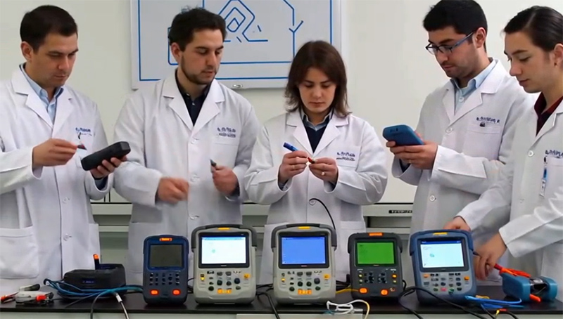
What Is the Best Way to Integrate Testing Tools with Network Equipment?
Using fiber optic testing tools to work in conjunction with CLI commands on network devices creates a powerful combination for testing SFP compatibility and performance. Given a choice, it is a better diagnostic process akin to having a diagnostic tool in the car as well as the onboard system for a full overall health checkup.
The first step is to utilize the CLI of the device to obtain detailed information on the SFP. By using commands, you can see real-time data (Tx/Rx optical power, temperature, voltage, bias current, etc.). These results are complementary to those from fiber optic testers and give a health status snapshot of the SFP module.
The next step is to use the CLI command show inventory or show idprom interface [interface-id] to validate the vendor of the module, the part number, the serial number, and its capabilities. This part of the test is essential, as it will validate that the module has specifications in compliance with the vendor’s requirements for the network equipment.
This is a critically important step in the SFP compatibility test to identify unsupported or counterfeit SFP modules that trigger network vulnerabilities. Using CLI diagnostic commands in conjunction with physical testing instruments ensures that you have a way to validate that the SFP is recognized and operating within parameters.
As an example, if the CLI indicates the laser bias current is abnormally high, but you are getting a normal reading from the optical power meter, that may be an indication that you have some sort of imminent hardware failure. Furthermore, many CLI logs will show link errors detected, or unsupported transceiver warnings, again giving you a way to identify and isolate faults.
One of the best features of this is that you can filter the logs with commands like show logging | include transceiver, which can get you to the right interface more quickly. Adopting this integrated approach enhances accurate performance verification and greatly reduces troubleshooting and guessing!
By combining CLI commands with fibre optic tester results, these professionals gain a greater understanding and confidence when determining SFP health and interchangeability with other devices!
Best Practices to Integration:
- Use CLI commands on equipment while completing the fibre optic testing process; for example, showing interfaces “<< transceiver detail >>” for a fibre device.
- Cross-reference vendor part numbers with inventory commands for compatibility and interchangeability.
- Take advantage of showing error logs with the CLI commands and map that with your physical testing data.
- Use your combination of information to establish a possible equipment failure like SFP decisions before service failures!
Integrating CLI commands for SFP with industry-accepted test equipment is a very good way to keep a fibre network performing optimally.
How to Use This Guide to Guarantee Every Fiber Optic Link Is Reliable
Dependable fiber optic connections provide the very foundation that enables highly reliable communication networks. Regular and accurate testing provides a safety net for potential failures before they impact critical data streams. Think about this just like “Wellness Checks” that ensure the network stays healthy and robust.
The continual use of SFP test equipment and optical test procedures to objectively assess each SFP module in the field, via a systematic test approach, ensures each SFP module in a fiber optic link meets a performance standard. Coupling the objective diagnostic data with visual inspection data, while monitoring CLI commands, allows a complete 360-degree perspective of network health. Collectively, this approach will eliminate “downtime” and costly repairs.
When performed consistently using valid test results, proactive maintenance is a reliable method to maximize module life and ensure peak signal integrity. In sophisticated optical networks, this discipline of perfect test results and troubleshooting is the determining factor for consistent, stable high-speed connectivity.
Once adopted, operators can begin the transition from being reactive to preventative, with every fiber optic test being a step along the path to a more reliable, future-proof system. Solid testing protocols and budgeting can enable a network to achieve dependable, consistent high performance each time.
