How to Stabilize Vibration in a 3D Drone Printed Fiber Optic Holder
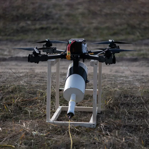
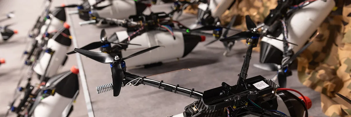
You apply the gas pedal to one half, and the display starts to undulate. The picture quivers like molten glass, your fiber link is unstable and for a moment, the flight feed becomes less clear. The drone’s interior is perfect, the motors are silent, the propellers are rotating without any friction and the tuning is very stable. But nevertheless, the picture quivers as if the camera were not securely attached.
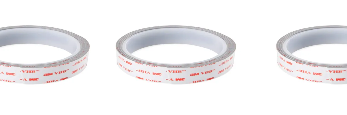
Issues with the electronics are seldom found and most of the time, they are hidden in the mount itself. A 3D printed holder for fiber optic drone transceivers that is either too rigid or too thin does not absorb vibrations like a tuning fork, but instead picks up vibrations and transmits them to the optics. The vibrations at specific motor speeds correspond exactly to the frame’s natural frequency, amplifying the movement rather than damping it. As soon as the origin is known, the repair goes on to be easy. Swap out the inflexible PLA for the PETG and construct a gyroid filled support to absorb the resonance. Moreover, a 90A TPU plus a 1mm VHB layer for joint vibration blocking is to be used—especially helpful when you’re already dealing with field issues like cables snagging on trees.
 Why PLA Acts Like a Tuning Fork
 Why PLA Acts Like a Tuning Fork
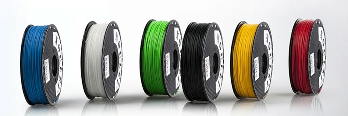
PLA, when printed, looks flawless—layers are smooth, edges are sharp, and corners are clean. But this flawlessness is a decoy inside the drone that reveals a weakness. The substance is very hard and fragile. When the motors’ vibration passes through the frame, PLA acts as a mirror to the energy and does not absorb it. This leads to continuous ringing, which imparts micro-vibrations directly into the camera or fiber connection. The test results of two identical mounts are the same. One made of PLA vibrates very loudly at specific motor speeds, practically reproducing every vibration it gets. On the other hand, the mount made of PETG bends a bit when stressed and therefore dissipates the energy much quicker.
This property of PETG reduces the vibrations transmitted to the camera by multiple folds, thereby ensuring sharpness of the image even in sudden changes of power. Besides, heat makes things worse. Around a hot video transmitter, PLA loses its structure, bends, and ultimately breaks apart. Up to a certain temperature, PETG is the stronger material and does not change its shape. For professional construction, the use of PLA should be restricted to prototypes only, it should never be used in mounts that are ready for flight.
How a Gyroid Sandwich Traps Resonance
 How a Gyroid Sandwich Traps Resonance
The majority of the builders presume that installing a harder mount will eliminate the vibrations; therefore, they go for a 100% infill. In reality, the vibrations are not reduced but rather transferred when using a completely solid holder, similar to a bell. A gyroid sandwich reverses that signal by introducing a balanced design of structure and flexibility. Under this arrangement, the outer PETG layer serves as a sturdy frame holding the fiber optic connector in place.
The inner gyroid core, printed with lower density, slightly bends and spreads the vibration through its patient geometry. When the energy comes into the mount, the pattern divides it into smaller waves that die before touching the optics. The principle is the same as that utilized by aerospace engineers in lightweight composite panels. They prevent resonance from traveling further by capturing vibration in internal cells. The gyroid sandwich has the same effect—clearer footage, less weight, and a lower chance of the jello effect in HD video.
How to Slice and Print the Gyroid Sandwich
The success of a functional gyroid sandwich is completely reliant on the correct slicing. Start by making two or three PETG wall perimeters—just enough to support the piece without overly solidifying it. Do not use very thick outer layers as they might hinder flexibility. Adjust the infill density to a value between 20% and 30%, with a choice of either a gyroid or grid pattern.
The selected density range permits the internal movement that absorbs motor vibrations to function well. For increased control, place the targeted damping zones directly under the screw mounts or close to the thin arms. In PrusaSlicer, position a modifier at the bottom and apply a gyroid infill of 15% to 20% to that area. In Cura, build a modifier cube for the same purpose.
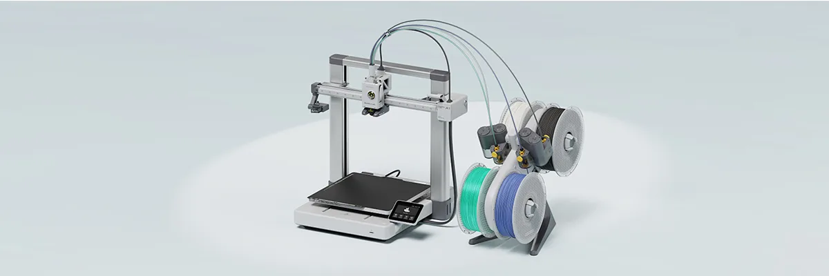
If printing with a multi-material printer, assign TPU to the damping areas and maintain the PETG for the shell. Solid sections should never be printed at full density as they trap vibrations and render the flexible core useless. The combination of selective structure and soft reinforcement keeps the performance balanced.
What 90A TPU Does—and How to Test It
 What 90A TPU Does—and How to Test It
The TPU hardness chosen is the one that decides whether the mount will filter the vibrations or transfer them. The sweet spot is approximately 90A on the Shore scale—hard enough to maintain the fiber connection but still soft enough to soak up the buzzing. The 85A grade, being softer, will eventually sag and thus lose its perfect alignment with time. The 95A grade is harder and has the feel of hard plastic, making it impossible for the cushioning to be felt.
Even without a durometer, the fingernail test is a good method to let you know the hardness of the material. Here are the steps:
- If only a small impression is made on the pad, it means the material is too hard.
- If the pad is completely pressed down by the nail, leaving a mark, it means the material is too soft.
- If the pad is only slightly pressed down by the nail and then quickly rebounds to its original shape, that is your 90A benchmark.
After confirming the hardness, put 90A TPU pads or washers under each mounting foot. They will create a compact yet soft layer that separates the vibrations of the frame from the camera, but at the same time, there will be no loss of optical alignment due to the tightness of the layer.
How 1 mm VHB Tape Becomes a Vibration Circuit Breaker
 How 1 mm VHB Tape Becomes a Vibration Circuit Breaker
Vibration locates its most convenient escape path right at the carbon frame-printed mount junction. The buzzing of the motor, which is the main source of noise in this assembly, is allowed to reach the whole assembly through the direct contact of metal and plastic. However, when a VHB tape layer of 1 mm is added, the situation is reversed. Acting as a tiny mechanical fuse, it’s strong in shear but soft in compression, enabling it to handle the structural load while blocking the flow of vibration.
Cover the entire mount base with tape, a physical feat, instead of only taping the bolt sites. Gently screw it upwards until the tape is compressed slightly, holding the mount securely but still allowing some movement. If torqued beyond this, the tape will become compressed, and the damping weakened. The objective of the mounts is to be in nearly perfect equilibrium; not rigid, yet secure.
Which closely resembles the way vehicle manufacturers put together dashboard material in use: using VHB tape to attach various parts to the main structure, each layer of adhesive serves as insulation to buzzing or vibrating components, without sacrificing strength. While vast toward drone applications, there are pretty much the same manners with the neat video feed or steady motion picture. Waste heat, if not applied carefully, can negatively affect the overall health of the aircraft components: a nearby video transmitter could heat the joint over time, and the adhesive would grow weak. Adhesive tape, if there is evidence of weakness, may have to be replaced once each year or each time after extreme heat is suddenly applied to it (flight).
How to Diagnose Shake in 5 Minutes
 How to Diagnose Shake in 5 Minutes
Diagnosis of vibration does not need anything special like lab equipment or vibration sensors because within just a few minutes of testing, it will reveal itself. It usually involves flying and doing a quick hover and throttle sweep while capturing your own flight. On studying the footage, one might notice blur or a slight wobble somewhere, and that will be the vibration area. Next, the propellers should be removed, and the drone placed over a stable surface.
Run the motors slowly and touch the frame and fiberglass. A very fine high-frequency buzz means that the mount is too thin or rigid. Soft, consistent pulses around screw holes tend to signal soft or irregular contact, which is associated with misaligned components or too much torque on joints. Close your eyes for analysis.
If there is no visual impairment, you should then feel nuanced changes of tone and texture in your fingertips, which would be compared with what you have seen in the footage. If it so happens that vibration starts at mid-range throttle and feels twingy, reprint it in PETG or play with infill patterns. If vibration feels dreary and slow-mannered, then you can go after damping layers or materials like TPV or VHB as the next step in rectification. After having completed 5 minutes of work, now you have rational clues for your tuning, saving you from the over-abundance of trial and error.
The Four Practical Steps to Kill Vibration
Most often, fixing vibration depends on a step-by-step intervention: an operation consistently building up reliability toward the camera feed-in quality that circumvents extensive unfixable modifications.
Step 1: Replace the material. Reproduce the mount in PETG but keeping its geometry unchanged. The elasticity of the material effectively eliminates the resonance at mid-throttle and the ring created from PLA, while still maintaining the original geometry.
Step 2 – Reshuffle the structure. Hardly two to three walls and set the gyroid infill to at least fifteen to twenty percent with the synergy intended, primarily, for the base and arm junctions. If your printer is dual-extruding, a bit of TPU goes a long way. This is very useful for adding damping to the mount.
Step 3 – Establish your cushioning. Once the printed material scene is set, you must add TPU washers or large under-masks. Never tighten bolts for the large or small components to force the model structure when slightly heated and then carefully spaced. TPU works fine at 90A.
Step 4. Use a strip of VHB tape, having a thickness of 1 mm, placed beneath the mudguard. Put some pressure with the screws so that the supports can break the coordination between the frame and the holders.
For these adjustments, repeat the levitation and fingertip tests. A combination of steps one and two will correct the problem, offering catastrophic evidence of the mammoth success of minor design alterations.
Why the Fix Works and What to Remember
 Why the Fix Works and What to Remember
The vibration itself will never be your enemy. It is, rather, just how easily it traverses the different paths established by a structure, not through vibration in general. Greater dampening in selected spots causes the whole condition to disperse a bit and smooth down. In contrast to brittle materials, which highlight resonances more compared to PETG, the gyroid sandwich would weaken and redirect the energy towards the inside where it can die, while the TPU and VHB together depend on each other to prevent any residual energy from reaching the optics.
All these changes will convert harsh vibration into a nice hum. Do a quick touch test whenever you notice a tremor. It identifies new problems before they start showing up in video. You don’t really need a lot of PID tuning or expensive parts; all you really need is smarter control of modeling and material activity. Once correctly carried out, the fiber holder becomes not only a mount, but a channel through which the vibration is converted to silence.
Reference Sources
- PETG vs. PLA: Differences and Comparison:Engineering guide comparing PLA and PETG for 3D printing, highlighting PETG’s superior vibration damping and flexibility for drone mounts.
- Motor Soft Mount 4 Pack – 3D Printed TPU:FPV drone resource on TPU vibration dampeners, explaining how 3D printed soft mounts reduce shakes in camera feeds and holders.
- Composite Filament Materials for 3D-Printed Drone Parts:Academic study on PETG and TPU composites for UAV parts, focusing on vibration isolation and structural stability in drone applications.
- 3D Printing Drone Parts: How to Get Started:Comprehensive tutorial on 3D printed drone components, including vibration-dampening designs for mounts and stabilizers.
- Best Materials for 3D Printing Drone Parts:Expert overview of PETG and TPU for drone frames and holders, emphasizing shock absorption and resonance reduction.