Splitting Your Signal? How to Choose the Right Fiber Coupler (FTTH, Data Center & More)
Are you in the process of designing a Fiber to the Home (FTTH) network, but wondering how to split one fiber for multiple users? Or maybe you are operating a data center, and you would like to use a single signal to provide to different devices, uncertain of which of the many fiber optic couplers will work? These types of situations require a basic understanding of fiber couplers to ensure proper signal strength for network dependability and validity.
When it comes to proper fiber optic coupler selection, you will have to consider the effectiveness of the application in splitting and distributing optical signals without losing or interrupting the signal. If you choose poorly, the server signal will not be strong, there will be delays in transmission, and users will be frustrated.
Understanding the different types of couplers, as well as the number of ports or interfaces you want to match your specific situation, should help you feel more confident as you expand your understanding of fiber and couplers in applications. After you gain this insight into the various applications of fiber optic couplers, you can ensure that your FTTH or data center course of action has a good, healthy optical signal performance for future dependability.
How Fiber Couplers Work: Understanding the Science Behind Signal Splitting
Envision your optical signal like water circulating through plumbing. The fiber optic coupler operates like a splitter that splits the water flow to various outlets, controlling how the water moves through the plumbing system. The pipe splitter will model how the incoming optical signal splits into numerous fibers, and each output fiber will carry some fractional value of the total light energy.
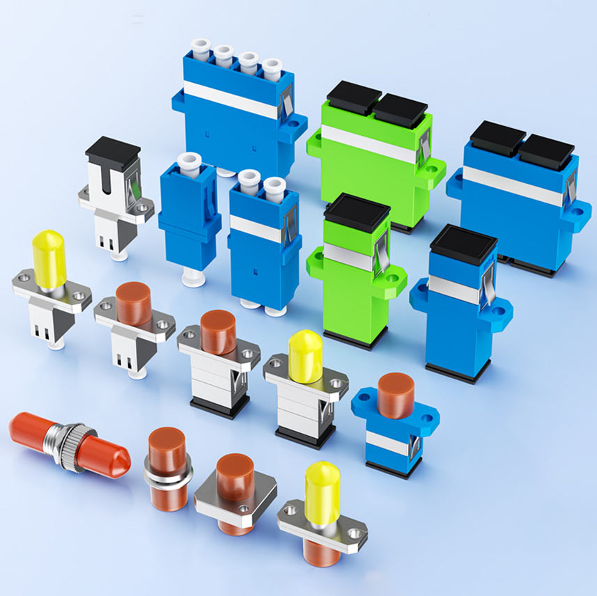
Fiber optic couplers are passive devices that distribute or combine optical signals, such as the one shown in the images of the optical coupler below. Equipment will also operate in a manner similar to some coupler configurations, such as 1×2 and 1×4. The 1×2 indicates that one input fiber is divided into two output fibers, while the 1×4 indicates that one input fiber is divided into four output fibers. The objective is that each port receives a portion of the incoming light while keeping the data in the light as pure as possible.
Inside the optical coupler are optical waveguides or fused fiber cores to guide the light to each output port in a proportional manner. As an example, if the input light signal were a 1×4 coupler, the input light signal would be equally divided into four output services at each output port, and each port output would contain approximately 25% of the original power level into each respective service.
Splitting light will bring about an inevitable reduction in the optical light level, which is known as insertion loss. Therefore, designers of these systems need to take this into account when installing optical equipment as well.
Knowing your number of ports and acceptable power levels will help you maintain reliable communication between the ports. Fiber to the Home (FTTH) and data centers are two examples of communication systems using optical couplers to feed more than one consumer or device in a reliable manner.

Your Coupler Checklist: Matching Port Counts & Interfaces to Your Needs
Choosing a coupler correctly depends on aligning port counts and connector interfaces with the demands of the network. The port count, which is the ability of the fiber to service users or devices, limits the number of users of the fiber, while interface compatibility facilitates communication.
| Port Count | Example Use Case | Key Consideration |
| 1×2 | Basic FTTH split | Low insertion loss, fewer endpoints |
| 1×4 | Small business or network nodes | Balanced signal strength and users |
| 1×8 | FTTH serving eight subscribers | Higher split ratio, greater insertion loss |
| 1×16 | Large CATV or data center setups | Requires signal power budget management |
Fewer ports, like 1×2 or 1×4, will allow for better signal strength as they are intended for deployments with fewer endpoints or over longer distances. More ports mean more users but also more insertion loss, so we need to manage optical power carefully here.
Couplers have multiple interface types — SC, LC, ST — and we need to ensure these match our fiber patch cables and all of our devices.
- SC: Most dominant, widely used in networking and telecom installations.
- LC: More dense (smaller cables), growing in popularity.
- ST: Legacy or industrial networks.
Having mismatched connector types will increase insertion loss and wear on your devices.
Key Recommendations:
- Determine the number of endpoints to select the right port count.
- Ensure the coupler interface matches the network hardware.
- FTTH deployments — typically use a 1×8 coupler with either SC or LC.
- Data centers — likely use 1×4 or 1×2 to minimize loss.
- Confirm insertion loss and power handling are within your optical budget.
Choose wisely, as attention to detail will ensure network stability and longevity!
Case Studies: Couplers in Action — FTTH, CATV & Enterprise Networks
FTTH Networks
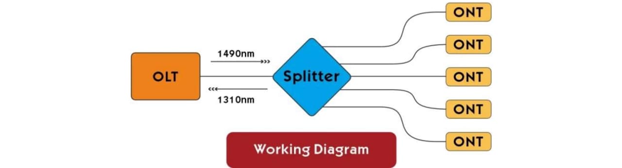
In the traditional setup for Fiber-To-The-Home (FTTH) technology, a single Optical Line Terminal (OLT) is utilized to output signals to all the optical network units (ONUs) at the homes of WVU subscribers. When a signal is sent from an OLT into a 1×8 coupler, the signal is split into eight different paths. Each path from the coupler goes to an ONU. This design facilitates lower installation costs and less expensive fiber infrastructure, allowing a source of broadband to be effectively disseminated across a wide area.
Cable TV (CATV) Systems
Cable TV providers distribute signals for video through fiber optic couplers. The coupler takes a signal from one source and converts it into signals for multiple subscribers. If the couplers are properly selected in size and geometry, there will be no perceptual degradation of the video signal for each subscriber. Couplers whose ports are also balanced will maintain appropriate signal levels for watching video over large coverage areas, such as preferred viewing in Huntington, WV.
Enterprise and Data Center Applications
In business or data center scenarios, fiber optic couplers are used in a similar fashion to distribute optical signals to many different servers and devices. A 1×4 coupler, for example, would split the bandwidth of a single fiber into four paths, which can be deployed for four different servers. This creates autonomy and redundancy for each server. With enterprise and data center applications, the focus is on uptime and low latency, where a coupler becomes necessary to efficiently distribute a signal to multiple devices while ensuring redundancy.
All of these configurations of networks benefit from a topology diagram showing the coupler locations and the source of the signal. This also reiterates the need for strategically placed couplers to achieve a network design while enhancing the effectiveness of the signal in the network.
The Performance Checklist: What Insertion Loss & Uniformity Mean for Your Network
Insertion loss is defined as the loss of optical signal power when the signal passes through a fiber optic coupler. You can think of insertion loss as a loss of signal energy due to the splitting of light. Inevitably, some of that light is going to be lost to absorption or scattering, meaning that the signal power will be lower at each output port. Insertion loss is measured in decibels (dB) and is a key factor in determining your network performance and effectiveness in maintaining communication.
Uniformity refers to how the optical power is distributed evenly or not among the output ports. Good uniformity means that the outputs are getting good power levels relative to each other. Poor uniformity implies that some users or devices will receive lower power signals than others; this can lead to variability in performance and possible connection issues.
In addition to insertion loss, high levels of insertion loss will lower signals received by a receiver, leading to higher error rates, or even a loss of connection. Furthermore, uneven uniformity can frustrate users if they observe poor signal quality, and their seamless experience becomes threatened.
Using couplers with minimal insertion loss will help maintain a solid signal level, while high uniformity means the end-users will experience consistent performance across all ports. Always consult the manufacturer’s specifications, and in many cases, you will find a level of loss that is near what should be expected under theoretical splitting, along with a narrow range of uniformity.
Final Thoughts
Selecting a fiber optic coupler is as simple as confirming that the number of ports and the connector interface style will work. Considering the performance characteristics of the coupler is important to ensuring that the insertion loss and uniformity will meet your specific network situation.
Knowledge of fiber optic couplers’ capabilities is also valuable when considering the trade-off of the number of ports regarding insertion loss and uniformity.
Reviewing use cases for fiber optic couplers with FTTH, CATV, and data center applications demonstrates the role of the coupler in maintaining high-quality, reliable communication throughout the network. Finally, considering factors about insertion loss and uniformity is also a valuable consideration for maintaining reliable communication across the endpoints throughout a network.
This information will give network designers and technicians the ability and confidence to select a fiber optic coupler that maximizes performance and plans for the future of optical networks.