How 10G SFP+ ER Modules Enable Long-Distance Optical Link Design and Deployment
Long-distance optical links are vital for enabling the spread of high-speed networking, but they come with unique challenges in both design and deployment. The 10G SFP+ ER module is one of the viable solutions to extend data transmission distance capabilities to an impressive 40 kilometers (24.9 miles) over single mode fiber. In use, the 10G SFP+ ER module operates at a longer wavelength in conjunction with improved technology and distinguishes itself in performance from the traditional LR module over longer distances while maintaining superior signal integrity.
This guide will explore in depth the technical implementation, design considerations for deployment, and best practices for the 10G SFP+ ER module. Data on a deployment’s performance of a generic 10G SFP+ ER module is shared through case studies, which can help you make better decisions about deploying and purchasing the modules. Understanding the differences in the design and performance of the SFP+ ER and SFP+ LR variants can maximize the performance capacity of long-distance optical networks and optimize your dollar spent.
This document will take you through designing your fiber link, monitoring techniques, troubleshooting, and future-proofing your network, which will enable a better understanding of 10G SFP+ ER modules as well as maximize your network potential for any use case.
What Is the 10G SFP+ ER Module?
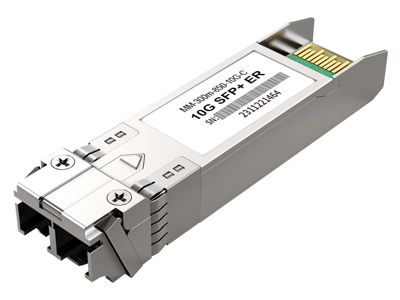
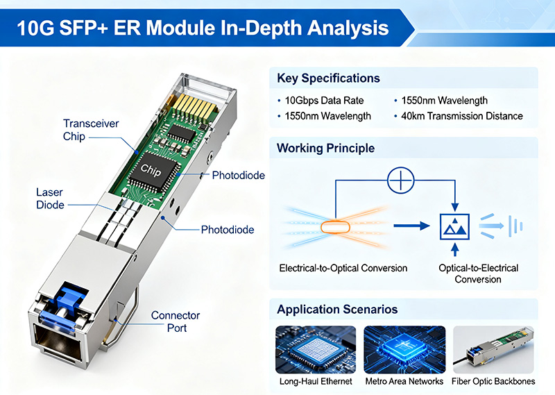
The 10G SFP+ ER module is designed to transmit data over long distances of up to 40 kilometers. Utilizing a wavelength of 1550nm, it is compatible with single-mode fiber. Signal attenuation is lessened significantly with single-mode fiber as opposed to using multimode. This makes the 10G SFP+ ER a fit for applications which require longer distances that standard enterprise connections do not provide.
The 10G SFP+ LR module transmits at 1310nm for distances up to 10 kilometers. The 10G SFP+ SR transmits over distances of 300 meters at 850nm utilizing multimode fiber for short-haul links. The 10G SFP+ ER uses 1550nm of light, thus reducing fiber losses due to higher optical power output. Therefore, the 10G SFP+ ER module is a good fit for metro and campus networks that require reliability over long distances for communication.
One clear advantage of the 10G SFP+ ER versus the LR or SR is the optical power budget and receiver sensitivity. Both the optical power budget and receiver sensitivity will help maintain signal integrity over a long distance when attenuation can impair data quality. These benefits will improve reliability for networks with wide campus coverage or that connect centralized remote data centers.
Below is a table comparing key specifications and typical application use:
| Specification | 10G SFP+ ER (1550nm) | 10G SFP+ LR (1310nm) | 10G SFP+ SR (850nm) |
| Fiber Type | Single-mode | Single-mode | Multimode |
| Maximum Distance | 40 km | 10 km | 300 m |
| Typical Application | Long-distance links | Enterprise LANs | Data center short links |
This comparison highlights the ER’s targeted design for long-distance requirements, providing networks with both extended reach and reliable performance while maintaining cost-effectiveness compared to alternatives.

How Does the 10G SFP+ ER Module Work?
The 10G SFP+ ER module is a small transceiver that converts electrical signals into optical pulses and back, allowing for high-speed communications over long distances. The transmitter uses an Electro-absorption Modulated Laser (EML) diode, which combines a continuous-wave laser with a modulator capable of changing the intensity of light at a rate of about 1550nm, which has low attenuation in single-mode fiber. The transmitter’s fast modulation creates precise optical pulses that minimize distortion.
The receiver uses photodetectors (PIN photodiodes or Avalanche Photodiodes [APD]) to reconvert the light signals back into electrical signals. Avalanche photodiodes, or APDs, have higher sensitivity because of an electric avalanche process inside. The APDs can also detect very small signals after they have traveled a long distance in the fiber.
Another major improvement is the Digital Diagnostic Monitoring (DDM) capability. DDM continuously checks several key limits, such as TX and RX optical power, laser bias current, voltage, and the temperature of the internal components of the module. With DDM, operators have live data about the health of the component, and they can look for problems, such as dropping power or climbing temperature, before the equipment fails and creates an outage.
The table below provides a brief overview of each major component of the module’s circuitry and its benefits to simplifying its considerable and complex internals:
| Component | Role | Benefit |
| EML Laser | Modulates light at 1550nm | Enables long-distance, low-loss transmission |
| APD Detector | Senses low-level signals | Enhances sensitivity, maintaining signal quality |
| DDM Function | Monitors module health | Provides real-time diagnostics, preventing failures |
Collectively, these technologies compose a balanced transceiver that achieves high data quality and uptime far out to extended optical runs. EML’s stable laser source, APD’s sensitive detection, and DDM’s monitoring capabilities provide networks with trustworthy, transparent long-distance communications.
What Are the Design Essentials for 10G SFP+ ER Long-Distance Optical Links?
When planning for long-distance links using 10G SFP+ ER modules, effective design starts with the fiber type and determining the proper loss budget to ensure reliable data transfer.
Choosing fiber type is largely dependent on OS1 and OS2 single-mode fibers. OS1 will generally find attenuation around 1.0 dB/km, making it an acceptable choice for indoor or premise installations. OS2 will report lower attenuation around 0.4 dB/km, making it more favorable for outdoor facilities and long-haul cable lengths. Because there is an advantage to OS2’s lower losses for a 40 km capability with 10G SFP+ ER modules, it is no surprise it may be the better option for our network.
Loss budget includes fiber attenuation combined with connector insertion and splice loss between the transmitter and receiver. Using a typical 40 km OS2 fiber link, the loss budget would include total fiber attenuation of about 16 dB. Adding in expected connector losses (about 0.3 dB per LC connector) and splice loss to the overall estimation provides a measure of upper-end losses acceptable to not compromise receiver sensitivity.
Below outlines the major steps in optical power budgeting:
- Calculate the total fiber attenuation by multiplying the fiber length by the attenuation rate.
- Add up all insertion losses from connectors and splices.
- Check that the module’s output power minus total loss is still above the receiver sensitivity.
Choosing connectors is not an insignificant choice; for example, while LC connectors are a standard choice for 10G SFP+ ER modules, they all contribute small additional insertion losses. By frequently inspecting and cleaning connectors to maintain a clean surface, unexpected power loss will be greatly reduced and will also help stabilize the link.
Other installation considerations:
- Use OS2 fiber for all outdoor or metro applications to maintain low attenuation.
- Loss budget calculations should be done before design is finalized; work should not progress with a loss budget that is overrun.
- Remember to handle fiber properly; tight bends or microbends will affect signal quality.
| Design Factor | Considerations | Impact |
| Fiber Type (OS1 vs OS2) | Attenuation rates, installation context | OS2 fiber recommended for maximum reach |
| Link Loss Budget | Fiber attenuation, connector and splice losses | Maintains adequate optical power at receiver |
| Connector Selection | LC connector cleanliness and quality | Reduces signal loss, enhances reliability |
| Installation Quality | Proper fiber handling and testing | Avoids faults and preserves signal integrity |
Incorporating these priorities into fiber link design ensures 10G SFP+ ER modules maintain excellent performance over long distances.
How Can Network Performance Be Optimized and Faults Effectively Troubleshot?
To ensure peak network performance while using 10G SFP+ ER modules, you will need to monitor continuously and systematically troubleshoot to quickly locate and correct a failure.
The foundation of the monitoring and troubleshooting procedure is Digital Diagnostic Monitoring (DDM). The DDM features report optical power, module temperature, and bias current as continuously generated values, which provide early warning of potential module issues or degradation.
The key monitoring features are:
- Optical Power: A significant drop in optical power reports an issue, verifying potential fiber damage, dirt on the connectors, or misalignment.
- Temperature: Prolonged temperatures may result in shortened component lifespan and signal degradation.
- Bias Current: The bias current readings will show variation, and aged or degraded components may show an increase or decrease in reported bias current.
When problems occur, these principles can guide the troubleshooting workflow as follows:
- Module Not Recognized: Follow the physical workflow. Physical seating and compatibility are the primary causes of module recognition failure. Clean the connector(s) and reseat the module.
- Link Degradation: The DDM or existing optical power meter will assist you in determining if the optical power level is correct. The fiber ends can be cleaned and inspected after fiber termination, with a fault locator or OTDR.
- Signal Loss or Errors: As with fiber degradation, improper fiber bends and damaged fiber must be examined closely. This is particularly true if the patch cords are suspect.
As you can see, digital diagnostic monitoring coupled with physical test instruments, like power meters and fault locators, expedites your troubleshooting and ultimately reduces repair time, minimizing your overall outage time during peak use.
| Trouble-Shooting Step | Action | Objective |
| Monitor DDM Parameters | Evaluate power, temperature, bias current | Detect early failure signs |
| Clean and Reseat | Clean connectors, reseat the module | Restore good physical connection |
| Use Power Meter | Measure optical signal strength | Validate loss budget compliance |
| Employ Fault Locator | Locate fiber breaks or bends | Precisely identify physical faults |
Combining continuous monitoring with targeted troubleshooting safeguards the long-distance link performance using 10G SFP+ ER modules.

Why Do Compatibility and Procurement Matter? How to Avoid Risks and Control Costs?
When implementing 10G SFP+ ER modules, an appropriate evaluation of compatibility and procurement strategy is a key consideration. The array of manufacturers and hardware platforms adds layers of complexity relating to interoperability, which, if not addressed effectively, can create link instability.
Differences in firmware and hardware implementations of, potentially, IEEE-compliant products can introduce timing issues, differences in signal strength, or fail to handle a particular protocol when functioning with various vendors’ equipment. The only way to ensure compatibility of an SFP+ ER module is to test a product to establish a baseline or rely on a vendor’s certification or product assurance.
Third-party modules may be very appealing due to their cost savings but may also present some quality assurance and compatibility issues. Sourcing a third-party module will require work in sourcing from a reputable supplier who provides warranties on their modules or products that assure their compliance with a particular IEEE standard on documentation to lessen the chances that their module will cause a network failure.
Procurement considerations should balance multiple lenses:
- IEEE Compliance: Formal compliance with the IEEE standards provides a baseline for interoperability and supports operation without interruption on a switch.
- Cost: Consider the total cost of ownership, including the failure rate of a module you are reviewing and the monthly, quarterly, or annual energy consumption, as well as any replacement fees for the duration of the procurement of that module. Identify the least cost or best quality.
- Maintenance: Long-term maintenance includes a vendor’s ongoing support of their products after the module is deployed or operational; lifetime availability or uptime of that module or product within a supply chain; and the frequency of replacing that module or product, as it is critical to reduce the impact of network failure operations.
| Evaluation Factor | Considerations | Effect |
| SFP+ ER Compatibility | Certified interoperability, network tests | Guarantees smooth multi-vendor operation |
| Third-Party Supplier Quality | Reputation, warranty, adherence to specs | Reduces procurement risks |
| Total Cost of Ownership (TCO) | Price, reliability, energy efficiency | Optimizes investment over device lifetime |
| Support & Maintenance | Vendor responsiveness and stock availability | Minimizes downtime and expedites repairs |
Adopting a multidimensional procurement framework balancing cost, compatibility, and maintenance ensures robust, cost-effective long-distance link deployment.
What Lessons Can Be Learned from a Real Deployment Case of 10G SFP+ ER in a Campus Network?
A substantial university campus consisting of various buildings across 30 kilometers needed a reliable update of its inter-building network links. The previous technology had used 10G SFP+ LR modules, but it was determined that many of its inter-building connections were unstable and corrosion to the optical module caused signal degradation due to environmental stress and aging fibers.
In reaction to these complexities, the next network design included 10G SFP+ ER modules, replacing the LR modules, and used OS2 single-mode fiber design. The use of the ER modules provided an extended optical reach of 40 kilometers, removing the need for intermediate repeater solutions and simplifying the network design. The fiber link design was thoughtful and designed for low loss, the connectors were cleaned, and the install was completed with minimal insertion loss.
After the initial assessment, it was determined that there had been a 25% reduction in bit error rate (BER) due to improved transmission quality. In addition, the network downtime decreased by more than 40%, which is easily attributed to the ER modules’ real-time monitoring capabilities offered by the digital diagnostic monitoring (DDM) features of the ER modules that could detect faults as they emerged and prevent additional errors in downstream nodes.
As the campus environment is not without challenges, such as fluctuating temperature ranges and electromagnetic interference from equipment on campus, the modules handled the issues well due to their design and temperature rating.
| Performance Aspect | Before Upgrade | After Upgrade |
| Optical Reach | Approx. 10 km | Extended to 40 km |
| Bit Error Rate (BER) | Higher, erratic errors | 25% lower, steady |
| Network Downtime | Frequent outages | 40% less downtime |
| Maintenance Approach | Reactive | Proactive via DDM alerting |
This example highlights the benefit of choosing quality transceivers and maintaining a disciplined fiber network. Clean connections, OS2 fiber, and built-in diagnostic tools are best practices for a campus-scale fiber installation with an emphasis on high availability.
How Do OEM and Third-Party 10G SFP+ ER Modules Compare? Exclusive Performance Test Data
In order to assess the variations in performance between Original Equipment Manufacturer (OEM) and third-party 10G SFP+ ER modules, a methodical laboratory test was conducted utilizing a stable 40 km OS2 fiber link (under laboratory-controlled climate conditions). The results of the tests of bit error rate (BER), in particular, showed that the OEM modules consistently had low (<10^-12) BER, demonstrating near-perfect data transmission. Most of the third-party modules also sustained acceptable BER (<10^-9), although in some cases, the third-party modules approached this performance level (<10^-9), particularly under severe stress on connections.
Over extended periods of time, OEM modules proved to be at least as stable as the third-party modules, with output power variations of <0.2 dB. Some third-party modules demonstrated instability at levels as high as 0.5 dB, which could affect sensitive fiber connections. When it came to power consumption, the OEM modules were around 10 to 15% more energy efficient. This had the dual benefits of producing less heat and making heat management easier. Again, OEM modules demonstrated superior performance with less variability than third-party options, with some exceptions.
Lastly, OEM modules had wider temperature tolerances (operating reliably between -5°C and 70°C), while some lower-cost third-party modules could not reliably operate in these upper tolerances, which could impact link reliability under harsh environmental conditions.
| Parameter | OEM Modules | Third-Party Modules |
| Bit Error Rate (BER) | <10^-12 | <10^-9 |
| Signal Stability | <0.2 dB variance | Up to 0.5 dB variance |
| Power Consumption | Lower, 10–15% more efficient | Variable performance |
| Temperature Range | -5°C to 70°C | Narrower with occasional failures |
The evidence presented here shows that conduction from OEM modules maintains reliability and efficiency, which is paramount for mission-critical long-distance links. In some situations, a third-party module may be selected to save costs; however, it will not be subject to the same level of testing and verification to mitigate risk.
| Test Parameter | OEM Advantages | Mitigation Strategies |
| BER | Minimal transmission errors | Validate performance specs |
| Stability | Consistent optical output | Use DDM monitoring |
| Power Efficiency | Lower thermal output | Confirm power specifications |
| Temperature Tolerance | Wide operating range | Avoid budget low-spec options |
Network engineers must weigh performance consistency against budget when selecting 10G SFP+ ER modules.
Why Plan for the Future? How to Build a Future-Proof Long-Distance Fiber Network?
When building a resilient long-distance fiber network, planning ahead with the appropriate infrastructure and technology is vital.
Certainly, the gross reservation of additional fiber strands during conduit installation ensures you can scale capacity requirements when additional bandwidth is needed, without the expense of trenching. The foresight to have these fibers reserved means you have the ability to scale up bandwidth when needed, without the expense or difficulty of installing new fiber.
Selecting modular 10G SFP+ ER transceivers to maintain 10 gigabit modular fiber increases your capability to scale bandwidth at a pace that aligns with actual traffic growth, capital expense, and operational flexibility.
Keeping transceivers and equipment aligned can also reduce the risk of replacing hardware components or the cost of disrupting your services. Careful device selection today matures into future-proofing and aligning with next-generation modules.
When performing capital expense and operational flexibility estimates, conduct a cost-benefit analysis based on the total cost of ownership (TCO), which places an accurate value and cost balance for initial investment and longer-term cost savings with maintenance, energy savings, and reduced downtime.
| Strategy | Benefit |
| Fiber Infrastructure Reservation | Enables capacity expansion with minimal disruption |
| Modular Upgrades | Aligns costs with demand growth |
| Device Compatibility | Ensures seamless future integration |
| Cost-Benefit Analysis | Optimizes investment and operational costs |
Planning using these strategies supports sustainable, flexible networks built around 10G ER technology as a backbone.
Conclusion
10G SFP+ ER modules are essential to provide strong optical connections over distances up to 40 kilometers and do not compromise the integrity of the signal. The successful deployment of these modules relies on a solid technical understanding, careful design of the fiber link, as well as smart purchasing to keep the network redundancy and scalability at the forefront. By embracing these concepts, you can make an informed, future-proof investment in your network to address an evolving appetite for data.