Fiber Optic Fusion Splicing Guide: From Safety to Troubleshooting

Frustrated with splice failures or elevated loss rates? Regardless of your level of experience, creating high-quality, high-performance fiber optic networks requires developing your skills in fusion splicing. This guide reveals the secrets to fusion splicing with little fluff—just proven, straightforward techniques refined from years of work in the field. The guide provides the complete workflow, covering safety precautions, tool selection, fiber preparation, fusion operation, quality control, and troubleshooting. Following these processes will help you learn how to create high-performance, low-loss fiber optic splices that last!
Safety First: Practical Protection and Workspace Setup
There are inherent hazards that we cannot overlook when discussing fusion splicing. The fusion arc burns over 5,000°C and can cause serious burns in an instant. When stripping and cleaving fiber, fine glass shards can be released that, if not properly cleaned up and disposed of, can lodge in the skin or cause long-term damage to your eyes. To protect yourself, always wear industrial, high-rated safety goggles and shoes that have cut-resistant material in them.
You should always dispose of shards immediately and should have sealed fiber waste containers dedicated to this type of waste (ideally a fiber waste container) or a vacuum-type device to do so. Static electricity is an enemy of fiber optics and splicer electronics, especially in dry environments and/or air conditioning. Static electricity can build up in your clothes and body, so the use of anti-static wrist straps and/or an anti-static mat may help in preventing this from happening.
Always check battery or AC power stability, the condition of the electrode, and, of course, that all your tools have been cleaned and are working before you begin your work. Following practical steps like this reduces accidents and stabilizes fusion quality.
Fiber Stripping: Selecting Precise Tools and Techniques
Selecting the appropriate stripper will depend on the fiber coating diameter. This will typically be 250µm for bare fibers and 900µm for coated fibers. Reputable companies like Jonard, Fujikura, and INNO provide multi-hole strippers calibrated to those finishes, making nicks or damage to the fragile glass core less likely.
When stripping the coating, it’s important to apply a controlled, uniform pressure to do so without bending or twisting the fiber. You will be able to produce microfractures with too much force or twisting, which may not be visible to the naked eye but can severely affect splice quality. In general, the recommended strip length will be between 10 and 20 mm depending on the specifications of the specific fusion splicer.
With single-mode fibers, just like all fibers, care must be taken to handle the coating gently; in this case, it is thinner than multimode fibers. Achieving a steady fiber hold (if you have a steady hand and good ergonomic tools) makes the stripping more consistent and less error-prone when you are repeating the action multiple times.

Cleaning Fiber Ends: Effective Techniques Against Contamination
Even dust, ash, or oil at a microscopic level can greatly degrade the quality of the splice. Therefore, clean the fiber ends quickly and thoroughly. New, lint-free wipes soaked in 99%+ isopropyl alcohol are preferred for cleaning fiber ends. Clean the fibers from the coating edge to the cleave tip in a single downward stroke, without back-and-forth motion, as this may redeposit the contaminant to the cleaved end face.
If there is a tough contaminant that leaves a residue, like gel or oil, you will need to use a fiber cleaning pen or optical-grade fiber cleaning fluid. You can also use a low-power microscope or built-in camera on the splicer to visually inspect the cleanliness of the fiber end faces and check for dust, scratches, or oil streaks after cleaning, if necessary.
When working in a dusty or humid environment, make sure you cover the cleaned fiber with a boot immediately after cleaning and before splicing. This will help keep them clean until it is time to splice them together. If splicing for an extended period, consider re-cleaning the fiber end faces at intervals, such as every 5 to 10 splices, to maintain lower loss performance.

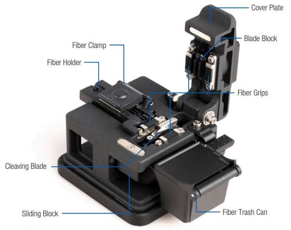
Using the Fiber Cleaver: Mastering the Perfect Cut
Select cleavers based on the task at hand—single-fiber cleavers are effective for repair work or low-volume jobs. Ribbon cleavers improve throughput by allowing multiple fibers to be scored in a single motion, which is especially important in dense installations with lots of fibers to splice.
Load stripped fiber into the cleaver’s groove so that the fiber lies flat without any bends or induced tension. Lower the cleaver arm gently until you hear a distinct “click,” which signifies that you have scored the fiber properly.
Microscopes should be used to verify that the cleave is flat, perpendicular (less than a 0.5° angle), and without chips on the cleave face or cracks in the fiber. Chip or crack imperfections will raise insertion loss significantly, typically 0.1 to 0.2 dB or more. Replace the blade at the first sign of wear to avoid expending time and costs on expensive rework.
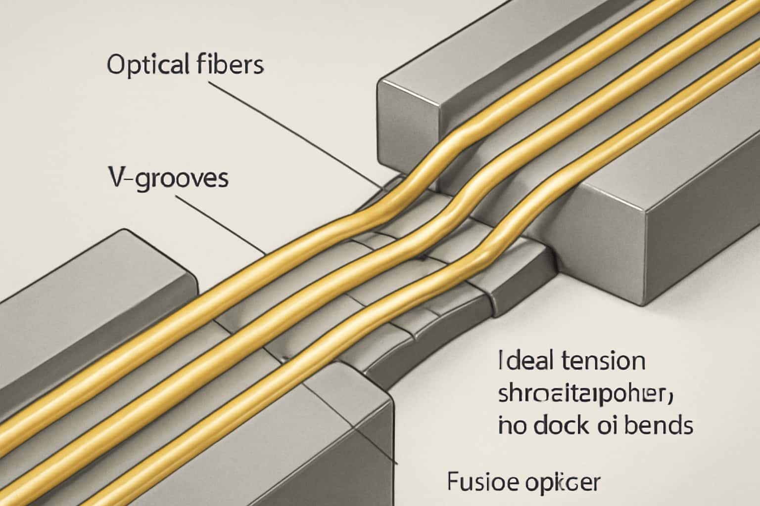
Loading Fibers into the Fusion Splicer: Precision Placement and Controlled Tension
Place the fibers carefully into the V-grooves of the splicer while aligning the fiber cores along the centerlines so as not to induce splice loss from misalignment of the fiber cores. In fact, even a small offset of the fiber cores can result in high splice loss.
Prior to fabrication, maintain a balanced tension—tension must be free enough to avoid causing a microbend or breakage but tight enough to maintain the fibers’ straightness. Forced tension may induce fractures or prevent the devices from completing the process, while too loose a tension will allow movement during fusion for the splice to take place.
Depending on the manufacturer of the fusion splicer, for example, Fujikura or Sumitomo fusion versions often automatically detect the fiber and align the fibers as part of the operating conditions; others require manual adjustments, and you should always clean out the V-grooves with alcohol to prevent misalignment from dust prior to fusion.
While it is outside the scope of this particular paper, please consult the splicing device manual for details on the best tension and placement for fusion to ensure optimal quality in the splice.
Fusion Process: Step-by-Step
Step 1: Arc Calibration
Turn on the splicer and then run the arc calibration to adjust the fusion parameters to local altitude and temperature—this is sometimes necessary to ensure a stable arc to produce the fiber fusion.
Step 2: Fusion
Insert the prepared fibers into the holders, and the splicer will automatically align the fibers and fuse them with a controlled electric arc. Watch the fiber display for bubbles, fiber offset, or arc stability issues that could signify a defective splice.
Step 3: Protection Sleeve Application
Slide a matching heat shrink protection sleeve over the splice point. The sleeve can then be heated in a heating oven or using a heat clamp to allow the sleeve to shrink evenly, creating a mechanical seal and protection against moisture.
If there are errors in the fusion point or surface irregularities (bubbles, inconsistent thickness of fusion), stop and reconsider the fusion. You may need to re-cleave the fibers and manually change arc power parameters as well, particularly if the weather is extreme, to ensure good fiber fusion.
Essential Post-Splice Testing: Key Steps
Phase 1: Mechanical Pull Test
Apply tension in the order of ~2 N to evaluate splice strength and durability, ensuring the integrity of the splice is intact.
Phase 2: Optical Loss Measurement
An OTDR or optical power meter will check the insertion loss. In most cases, our targets will range from 0.02 dB to 0.05 dB; if the loss exceeds 0.1 dB, the splice will require rework.
Phase 3: Visual Inspection
You will use either the built-in microscope or handheld scopes to identify bubbles, cracks, or misalignments.
When mechanical, optical, and visual tests are performed together, you will have a confident, field-ready, high-quality splice.
Field Troubleshooting: Diagnosing and Resolving Common Splice Failures
Here’s what high splice loss or failures are usually related to:
- Contaminated fiber ends— if you see that there is dust or oil, re-clean thoroughly.
- Poor cleaving— if you see chips, uneven surfaces, or if the angle is greater than 0.5°, pare down the cleaving.
- Equipment/Operator issues— replace dirty or worn-down electrodes, and clean the V-grooves.
- Environmental conditions— if it’s cold or humid, adjust the manual arc time/power to get better results.
Examples of the above:
- Splice has bubbles? Likely due to dirty fibers or worn-down electrodes—clean and replace if needed.
- Splice has loss greater than 0.1 dB? Likely due to misalignment of fibers because of dirty V-grooves or not calibrating the equipment correctly—clean the V-grooves and recalibrate the equipment.
More often than not, quick resets and maintenance can restore performance right on the job, minimizing downtime.
Practical Checklist for Every Fusion Splice
- Check the neatness of tools and workspace before doing the splice.
- Verify the stripping length and cleanliness of the fiber end-face.
- Position the fibers accurately and apply slight tension in the V-grooves.
- Perform arc test calibration; observe for an acceptable photo-fusion.
- Check visually; follow up with a mechanical pull test and an optical loss test on the finished splice.
- Securely install and heat the protection sleeve.
- Document splice information to track quality and for future reference.
By adhering to this disciplined routine, you will increase your chances of avoiding mistakes and subsequently increasing the reliability of your network.
Model-Specific Operational Tips & Differences
Core alignment splicing machines align the cores of the fibers utilizing sophisticated optical imaging, yielding splice losses of less than 0.02 dB, suited for high-speed long-distance applications. Clad alignment splicing machines align the fibers based on the outer cladding, which is a faster process and has average losses in the range of around 0.05 dB, suited for local and access networks.
Ribbon fiber splicing machines weld all the individual fibers (12 or more) at the same time, increasing production efficiency for data center and telecom installations. Single fiber splicing machines perform better on repair or custom projects where the sides need to be precise.
Each of the top brands of splicing machines are Fujikura, Sumitomo, and INNO, each of which has different features such as auto calibration, user interface, as well as different designs of the electrodes. It is worth your time to understand the features of the specific splicer you are using, to maximize splice quality, as well as to ensure you have an efficient workflow process.
Routine Maintenance to Ensure Field-Ready Splicers
Regular upkeep ensures the accuracy and longevity of your fusion splicer:
- Clean your electrodes, V-grooves, clamps, and screens routinely with alcohol wipes.
- Monitor electrode wear. Replace the electrodes when you begin to notice spark instability.
- Regular arc calibration is a good practice for overall fusion energy consistency.
- Maintain the splicer’s firmware to gain added enhancements and fixes.
- Tracking down occurrence errors and other anomalies is beneficial for early fault detection.
Planned maintenance mitigates the risk of unexpected downtime and provides consistent splice quality; both are especially important as you conduct fieldwork over time.
Precision and Consistency Yield Perfect Splices
Every fusion splice step requires attention to detail — from preparation through to testing. Attention to detail and practice ensure that what would be an ordinary splice becomes a solid, low-loss fiber optic connection. Consistent and repeatable practice also develops skills. Clean tools and an organized workspace support an equally reliable process.
Once you have mastered these skills, you will be more than an operator; you will be a professional engineer with responsibility for the quality and reliability of the critical fiber optic networks of tomorrow.