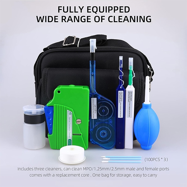
Fiber Optic Cleaner for FTTH/5G – From 5 min to 30s Cleaning, Zero Lint Swab Protocol
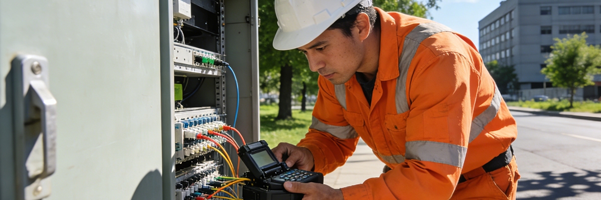
A fiber technician bending over a set of connectors next to a roadside telecom cabinet on an average summer afternoon finds himself surrounded by dust, sweat, and other contaminants. Every gust of wind brings with it fine dust particles that the technician must keep at bay, as well as moisture, which is of no concern when dealing with electrical components and installations. He wipes the connector, inspects it again, and then wipes it again. After five minutes of performing this task, a small smudge appears on the fiber connection he has just spent five minutes cleaning.
This is the unrecognized threat to fiber networks—fine dust particles, static electricity, and lint from clothing that undo all of the time and effort spent on installing fibers. Field technicians working on FTTH and 5G projects across the globe are faced with the same issues and frustrations. Wipes made from traditional materials (such as alcohol wipes) typically shed microfibers that contribute to these problems. Many solvents used to clean optical connectors tend to evaporate before they can be applied to a connector, creating a residue that results in poor signal quality.
To alleviate these problems, the 30 Second Zero Lint Swab Protocol was created to put an end to this cycle of contamination resulting in poor signal quality. The 30 Second Zero Lint Swab Protocol utilizes balanced solvent chemistry, lint-free cleaning materials, and rigorous timing to convert fiber connector cleaning from guesswork into a repeatable and predictable process of cleaning connectors. In independent trials conducted using IEC 61300-3-35 inspection standards, insertion loss (IL) measurements under 0.05 dB were achieved routinely, and the percentage of connectors that needed to be re-cleaned was reduced by over 60%.
 Field Dust and Heat Diagnostic Framework
 Field Dust and Heat Diagnostic Framework
Three common parameters define every outdoor fiber space: temperature, airflow, and contamination. When air temperature exceeds 35 °C as a result of direct sunlight, any isopropyl alcohol that would typically be used will evaporate before it can dissolve away any residue on that same ferrule. Additionally, when vehicle traffic passes by, it creates an airflow that carries contamination with it in the form of airborne dust, dirt, and other particles that can subsequently fall onto those newly exposed ferrules. The combination of the two factors mentioned can cause problems for even the most well-trained technicians trying to maintain consistency in their work.
Examples of this can be found in crews working in the Southern Hemisphere on the FTTH rollout for China Telecom, where crews now include a 10-second field check at the start of every job to check the weather conditions as well as humidity and dust flow. Crews will conduct this check using their heightened sense of touch to determine the surface temperature of the ferrule itself and then visually observing which direction the wind is blowing. Based on the results of this field check, technicians can determine if they need to provide protection for the exteriors of their cabinets or if they need to switch out the isopropyl alcohol they are using for a lower volatility, less gas-volatile solvent blend.
This simple assessment and decision can mean the difference between having one successful pass or needing to redo the fiber work due to a poor first pass.
10-Second Field Assessment
 10-Second Field Assessment
In the ten-second field assessment, the technician can make a quick diagnosis of the surface condition of the item by feeling the ferrule’s heat through touch; therefore, if the surface condition indicates that the item is still hot enough to maintain solvent for approximately ten seconds, then a solvent specifically designed to remain stable for approximately ten seconds would be used for this item, as this is sufficient to remove any oils from fingerprints as well as solidified dirt or grime. If there are fine particles floating in the air around the technician, they would select an electrospun polymer swab for use on the item, as they will collect dust particles through the bond created from surface tension rather than friction with the surface of the item.
If, after performing standard cleaning procedures on an item, the insertion loss remains at 0.3 dB or above, the technician will recognize immediately that the cause is the hardened residue caused by the exposure to both UV light and heat created from cleaning the item. Rather than repeat the dry wipe procedure again and again, the technician would follow the solvent-based cleaning process with a direct inspection of the item under the microscope. By using the “observe, adapt, verify” process, the technician is able to improve the speed at which they are able to perform their field cleaning processes.
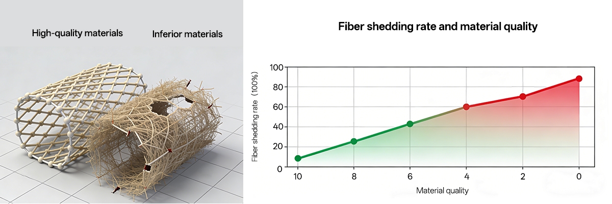
Lint Rate and Material Quality
 Lint Rate and Material Quality
The quality of the cleaning materials can also greatly impact the end result of cleaning. The most relevant field studies conducted on cleaning materials, alcohol wipes and electrospun nanofiber swabs, were completed using similar dust and heat variables. The findings were clear and straightforward. The traditional alcohol wipes shed approximately 5% of their own fiber during cleaning, leaving filament debris behind in the connector end.
These remnants cause blockage of the connector aperture and increased IL readings of approximately 0.25 dB. In contrast, electrospun swabs are composed of continuous bonded layers of polymer that create microscopic pores that act as capillary channels and prevent the masking of dirt and debris. Electrospun swabs shed nearly no lint (less than 0.2% per cleaning), contain and prevent the movement of dirt and debris from the cleaning surface, and provide an average loss of approximately 0.05 dB between inspections with the same consistency for many consecutive times.
The lack of lint on electrospun swabs decreases the chance of static-induced recontamination. For cleaning technicians, the result is continued clarity without the need for multiple cleaning cycles.
30-Second Heat-Resistant Protocol
 30-Second Heat-Resistant Protocol
In order to minimize manual process variation when evaluating IL, the Revised Solvent Formulation incorporates a 30-second process with precision-timed coordination of solvent action and physical movement. In high-temperature areas, the standard alcohol evaporates very quickly (2 to 3 seconds) but does not provide an effective solution for breaking up stubborn contaminants, while the Revised Solvent provides approximately 10 seconds of solvency and remains in operation for a longer period of time than standard alcohols. The time frame for using the Revised Solvent allows contaminants to be loosened with minimal impact due to the action of capillary forces and surface tension prior to the release of the solvent.
The first mechanical component of this new process occurs with the first drag of the cleaning tool from the inner center of the fiber to the outer edge. The process is deterministic when the timing of the mechanical action occurs in conjunction with the solvent’s time frame, allowing for one stroke to produce one result. In 30 seconds or less, including time for inspection and testing, technicians will be able to verify that the cleaning process has produced stable results by using a hand-held microscope and power meter.
IL readings have been recorded and consistently maintain an average of below 0.05 dB in both outdoor and indoor testing conditions, thus eliminating the uncertainty caused by operator variability.
Solvent Behavior Under Heat
 Solvent Behavior Under Heat
What we know about Solvent Control tells us why timing is critical. As the temperature increases from 25 °C to 40 °C, the evaporation rate will approximately double. If a product evaporates too rapidly, it will result in streaks on the item, which will scatter emitted light. If a product evaporates too slowly, it will allow dust particles to fall into damp residue.
Controlled volatility solvent blends are designed to help balance these two extremes. The drying profile for a controlled volatility product is evenly distributed, allowing for a sufficient amount of time between the time of application and full evaporation to maintain a uniform cover. Through an optical test done at several bench locations, it was confirmed that when using controlled volatility solvents, the IL Variance will remain within ±0.05 dB under simulated desert temperatures.
For the technician, there should be no surprises once the instrument is calibrated; the process remains constant regardless of climatic conditions.
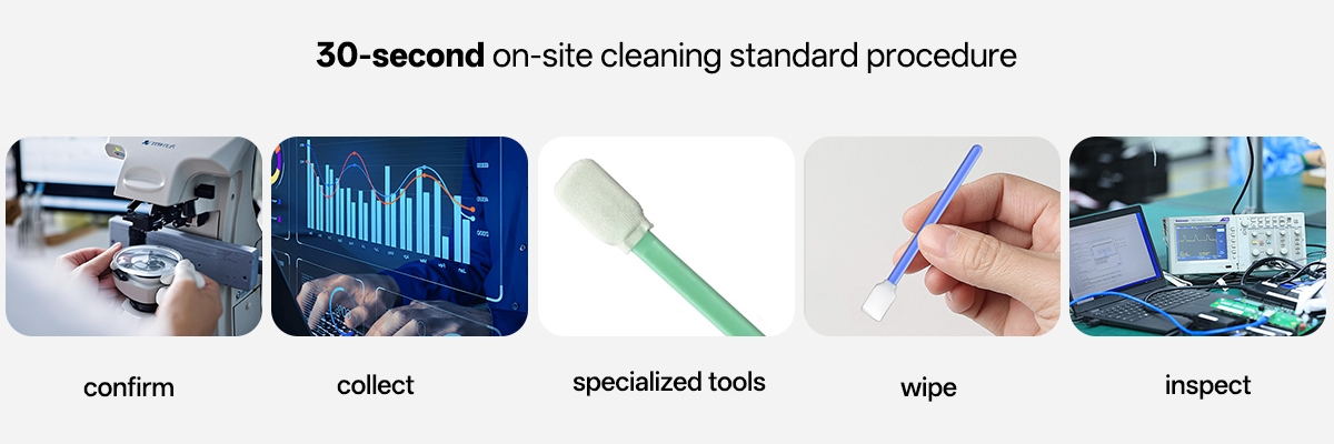
FTTH/5G 30s Field Clean Protocol
 FTTH/5G 30s Field Clean Protocol
As described in the preceding paragraphs, standardized cleaning cycles consist of a number of steps that follow a set process for successful cleaning. When starting a cleaning cycle, a technician typically inspects the connector under a microscope at 200× magnification. The technician will identify any haze or particulate on the connector. Using a baseline IL value to set the initial target, most technicians establish that their initial IL reading is around 0.2 dB.
The technician will then dispense a small amount (approximately 1 microliter) of solvent on the saturated tip of the electrospun swab. After 10 seconds of waiting for the solvent to dissolve the contamination, the technician uses the region at the tip of the swab and wipes in a smooth, direct motion toward the outside of the connector ferrule, avoiding any lateral movement on the ferrule surface. Next, the technician performs a half-rotation of the instrument used to clean the connector in order to create a better absorption area on both ends of the swab.
The technician then inspects the ferrule core for clarity, and if both the ferrule core is clear and the IL reading is below 0.05 dB after cleaning, it will be approved for connection. Technicians who have previously been trained in this routine achieve over 95% first-pass success rates for cleaning connectors. Additionally, instances requiring further cleaning to pass inspection have been reduced by approximately 70%.
Utilization of the following inspection-dwell-sweep-verify inspection cycle builds consistency and repeatability, as opposed to simply focusing on the speed at which the connector was cleaned.
Anti-Lint Performance and Wind Control
 Anti-Lint Performance and Wind Control
Light Breeze Can Ruin a Clean Interface on an Open Fiber Cabinet. All traditional wipes shed filthy-looking microscopic fibers that can drift and then settle back down to the surface again. Electrospun swabs completely eliminate all exposed threads so as not to be able to detach anything as they do when they are bent. All of the fiber strands in the fabric of an electrospun swab are fused together so they won’t detach at all.
Therefore, there is no shedding, and all debris is totally internalized. Microscope photographs taken over many hundreds of wipes show that swabs maintain the shape of their original design, as well as the ability to absorb liquid, after many hundreds of wipes. In FTTH deployments along the major highway system of Malaysia, many field technicians working at sites along the highway had no visible re-contamination after they converted from woven wipes to electrospun wipes.
Not only are electrospun wipes cleaner, but they stay cleaner for a longer duration of time than woven wipes, even when used with air that is heavily laden with exhaust particles.
Drag Technique and Field Results
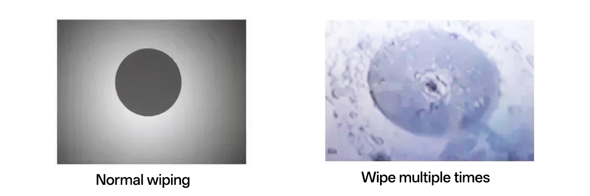 Drag Technique and Field Results
The practice of excessive wiping has been shown to have more negative than positive effects. Multi-pass cleaning techniques create additional static charges and draw contaminants into the inside of the fibers. Testing on different networks indicates that the calibrated single-drag technique is the most effective method of all cleaning techniques. Crews using this cleaning method completed cycles in approximately 30 seconds with a 95% immediate pass rate.
Crews employing a multi-pass approach required an average of approximately 90 seconds to complete the same cycle and still had a failure rate of approximately 30%. BOTTOM LINE: Disciplined rhythm will always outperform brute repetition in any cleaning process! By using a consistent timing and motion, engineers can maintain their solvents’ performance, minimize their fatigue, and reduce their wasted consumables.
Cleaning becomes predictable, repeatable, and in accordance with a standard quality control protocol.
Field Verification in Practice
Laboratories are no longer needed to conduct verifications. Today’s compact digital microscope can provide images with the same resolution as your laboratory-grade microscope, which means it will detect even one-micron particles. In addition, the ability to adjust the brightness of the LED light source reduces glare, so users can inspect connectors without the risk of visual fatigue. With the implementation of the IEC 61300-3-35, a pass of the verification process today means that there is less than 0.08 dB of light loss and no haze in the center zone of the fiber optic connector.
The verification process is a continuous loop of focusing the microscope on the fiber optic connectors, performing inspections of the fiber optic connectors, and confirming the inspection immediately after completion. A field technician trained on this process, on average, completes over 200 inspections per day. This eliminates the previous need to send all connector inspections to an outside laboratory before completing the installation process.
As Marcus Lee, a Senior Quality Assurance (QA) Supervisor for 5G installations throughout Southeast Asia, stated, “Our team trusts what we see at the site. If the microscope shows a clean connector, then the power meter indicates it is clean as well. There is confidence in this process.”
5G Backhaul Turnaround
Acceptance testing for a 5G Backhaul deployment along the coastline of China had been severely delayed for weeks due to repeated spikes in losses. Initial insertion loss values (IL) were at 0.10 dB immediately after being cleaned, but then increased to 0.40 dB shortly after cleaning was performed. Microscopic examination of the surfaces being cleaned revealed that the surfaces contained hardened residue that was caused by heat and exposure to UV (ultraviolet) light. The use of traditional wipes did not work to adequately remove the residue on the surfaces, but instead caused the distribution of the hardened residue across the surfaces.
To make things easier for the local team, they adopted the use of a controlled volatility solvent with the 30-second Zero Lint Protocol for removing the hardened residue from the surfaces. The IL (insertion loss) value on the first application of the controlled volatility solvent was reduced to 0.05 dB from 0.40 dB and remained stable when tested under continuous operation at 40 °C for a period of 24 hours. Follow-up measurements indicated no drift of the insertion loss after 24 hours.
The new cleaning procedure used by the local team has resulted in first-pass cleaning success rates of over 95% across all deployments in the outer region of China. The amount of consumable materials used in the cleaning procedures was reduced to nearly half of the previous amount. “It was a nightmare, it used to take us forever in the heat,” recalls Wei Jun, the field supervisor. “Now, we clean once, check once, and we’re done.”
The relief felt by all field personnel installing outdoor systems is reflected in the fact that the times before and after the installation of the new protocol are no longer compared.
Daily SOP and Long-Term Reliability
In order to maintain a consistent level of cleanliness, it is critical to establish regular cleaning protocols. Dust and static can quickly return to an area, therefore regular routine cleanliness is more important than the intensity of the cleaning effort. For example, using the 30-second rule for keeping the field clean will integrate easily into your company’s daily operations. As part of your daily routines before installation of each connector, an installer should ensure a full cleanliness check for each connector and verify that all connectors meet an industry standard based on insertion loss (IL) less than 0.05 dB.
As part of your routine to maintain compliance, approximately 15% of all connectors should be tested as spot checks to verify compliance using portable scopes. Monthly maintenance of field installations calls for restocking your solvent supplies, replacing old swabs, and checking for ferrule oxidation. A recent survey conducted over six months across 80 field installations showed that field teams with stringent maintenance practices consistently maintained average IL results between 0.12 dB and 0.44 dB, whereas sites that lacked consistent maintenance practices averaged an insertion loss of approximately 0.3 dB.
Fewer callback trips were made, and more time has been provided to maintain a stable network uptime. Weather permitting, outside cabinets located near heavily trafficked areas are inspected on an hourly basis. Indoor racks located within a data center have scheduled inspection intervals of up to three days, depending on the conditions of the facility. Controlled solvents used to perform optical cleaning resulted in approximately 10 times the period of optical consistency compared to legacy optical cleaning methods.
This was documented in a case with a network that performed uninterrupted for a full 24-hour period.
Insights from the Field
 Insights from the Field
In the U.S., utility contractor LumenCorp reported a reduction in total cleaning time per site by 50%, and new employees achieved veteran performance in only one training session. In Singapore, a network operations manager stated, “We converted approximately 50% of cleaning from guessing to scientific method.” Rather than aggressive scrubbing, the emphasis on process allowed teams to adopt a more consistent tempo. Similarly, managers saw comparable cost savings from conversion: fewer wipes, less solvent, and faster acceptance of completed work.
These marginal efficiencies multiplied into significant time savings on large FTTH deployments and thousands of dollars in waste material savings for many projects. The new discipline of cleaning provided technicians with increased confidence. It also changed the way technicians view cleaning; it is no longer an inconsequential part of their jobs. Instead, it has become a measurable component of their optical quality assurance.
Conclusion
Although technological advances play a role in the evolution of Fiber Connectivity, the greatest progress has come from developing best practices for cleaning fiber optic connections with minimal contamination and through increased use of preventative maintenance methods through proper technique and tools; stabilizing solvent dwell time to minimize lint release and create consistent motion allows FTTH and 5G cleans to achieve lab-grade clarity in the field. The rate of success for initial cleans compared to the original or historical method of using an alcohol wipe has increased from the historical seventy percent range to ninety-five percent.
In addition, the time spent recleaning has decreased by seventy percent, solvent use has decreased by forty percent, and the overall field performance has almost doubled. The entire training methodology previously took three days and now fits within a single day session. Any Network Provider can immediately implement this process using the existing methodology and tools made available to them for fiber optic cleaning: correctly verified lint-free swabs, balanced solvents, and portable magnification devices.
In order to implement this process, a Network Provider will not need to purchase any new devices; however, they will need to use proper discipline, observation, and timing in their performance. As fiber optic networks continue to expand into increasingly high-density urban areas with large amounts of data flowing and heavy amounts of traffic, it will become very important for Network Providers to ensure predictable levels of cleanliness from a technical standpoint, as well as to ensure that fiber optic signals traveling along these fiber optic networks are strong enough to allow the appropriate amount of bandwidth to transmit through.
Although the 30 Second Protocol Clean Method is not futuristic or technologically advanced, it represents what Engineers Value Most–Predictable Results, Lower Cost, and Reliable Performance. Each and every fiber optic connection that is cleaned using this Protocol brings the network one step closer to achieving Optimal State–One Wipe, One Clear Signal at a Time.
📚 Reference Sources
- EXFO: Sources of Fiber-Optic Network Issues in the Data Center – Connector contamination as top failure cause in data centers.
- IEC Webstore: IEC 61300-3-35:2022 – Visual inspection standard for fiber connectors, used in cleaning trials.
- Fluke Networks: Fiber End Face Inspections per IEC 61300-3-35 – Key changes for contamination detection.
- INEMI: Optical Connector Contamination Effects – Studies IL/RL impact from dust and oil.
- Chemtronics: Fiber Optic Cleaning Best Practices – Lint-free swabs and solvent protocols for low IL.
- Corning: Connector End-Face Cleaning Importance – Contaminants cause signal loss in networks.