


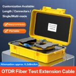

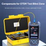
The problems experienced by OTDR technicians tend to be ubiquitous—the launch dead zone. In many instances, it is that initial 10–20 meters where high reflectance saturates the detector, which makes identifying any potential connector faults particularly difficult. The Fiber Optic OTDR Launch Cable Box will eliminate this issue.
The launch cable box connects between the OTDR and the network fiber. The fiber used for the launch cable box is a clean reference fibre that enables you to measure with precision the performance of the first connection that the OTDR reads. Therefore, you will never have to question whether a patch cord is causing the problem or if it is an actual fibre connection.
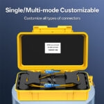
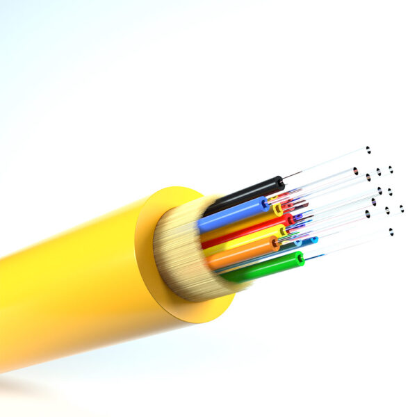
Single Mode G.657.A1 is rated for testing distances up to 50 kilometers and is intended for use in metro rings and FTTH backbones. Its bend-tolerant design is specifically optimized for close-quarters installation. Multimode OM1–OM4 is capable of testing data centre trunks and campus cabling. Both Single Mode and Multimode have stable loss characteristics and have no splices inside. As a result, technicians can utilize one cable type to cover all types of networks.
 Technical Specifications
 Technical Specifications
| Category | Parameter | Portable Box (≤2km) | Spool Series (1–50km) |
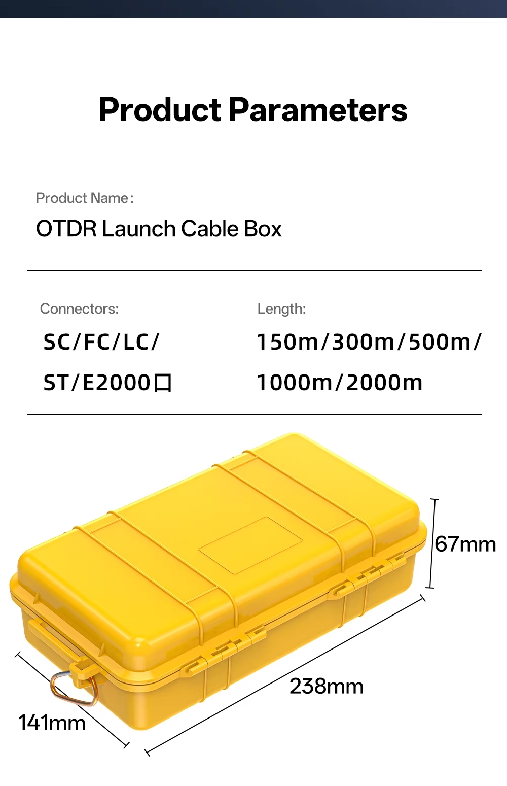
| Mechanical | Dimensions | 238×141×67mm | 300–500mm diameter spool |
| Empty Weight | 0.75kg | 5kg (blue spool), 12–15kg (white spool) | |
| Material | SR Polypropylene (yellow) | Rugged composite | |
| Environmental | Operating Temp | -40°C to +85°C | -40°C to +85°C |
| Storage Temp | -40°C to +90°C | -40°C to +90°C | |
| Protection | IP65 waterproof/dustproof | IP65 waterproof/dustproof | |
| Fiber Specs | Single Mode | G.657.A1 ≤0.35 dB/km @1310nm, ≤0.22 dB/km @1550nm, Dispersion ≤18 ps/(nm·km) | G.657.A1 ≤0.35 dB/km @1310nm, ≤0.22 dB/km @1550nm, Dispersion ≤18 ps/(nm·km) |
| Multimode | OM1 (62.5/125μm) or OM2/OM3/OM4 (50/125μm), ≤3.5 dB/km @850nm | OM1 (62.5/125μm) or OM2/OM3/OM4 (50/125μm), ≤3.5 dB/km @850nm | |
| Zero-point Uniformity | <0.05dB full length | <0.05dB full length | |
| Connector Performance | Return Loss | SM: UPC≥50dB, APC≥65dB; MM: PC≥30dB | SM: UPC≥50dB, APC≥65dB; MM: PC≥30dB |
| Insertion Loss | ≤0.3dB/connector (typ. 0.15dB) | ≤0.3dB/connector (typ. 0.15dB) | |
| Geometry | IEC 61755-1 compliant | IEC 61755-1 compliant | |
| Lead Strength | 100N short/60N long-term, 2m 3mm Kevlar buffer | 100N short/60N long-term, 2m 3mm Kevlar buffer | |
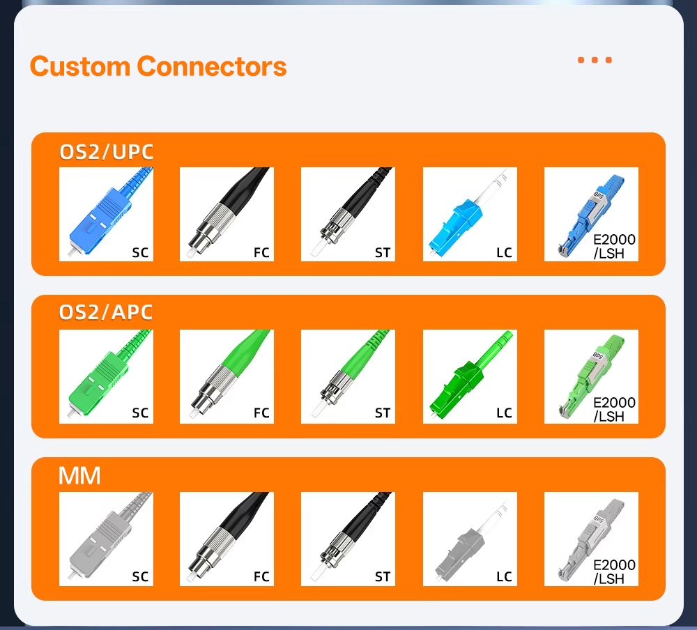
| 10 Types | LC/SC/ST/FC/LSH/E2000 | LC/SC/ST/FC/LSH/E2000 |
Single Mode vs Multimode Applications
The G.657.A1 Single Mode Cable is designed for telecommunications professionals. It can be used to test dark fibers exceeding 10 km in length or in FTTx PON configurations. The use of APC connectors minimizes back-reflection when testing in live networks. In addition to providing reliability when testing at 1550 nm, its lower chromatic dispersion ensures accurate OTDR measurements.
Multimode cables (OM1–OM4) are intended for data center and enterprise use. OM1 (62.5–125 μm) supports older 1G legacy networks. OM2, OM3, and OM4 (50–125 μm) support 10GBASE-SR and 40GBASE-SR4 links. All use UPC connectors matching standard MM transceivers. Both options eliminate potential confusion regarding dead zones. They share the same rugged casing; only the fiber core type and polish differ.
 Field Construction Details
 Field Construction Details
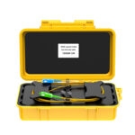
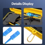
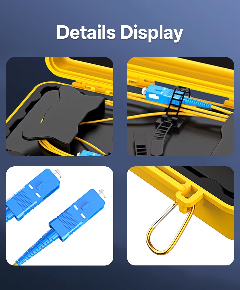
The metal retractor allows the user to pull the fiber smoothly without creating microbends. The integrated cable management system prevents tangling during installation. Line clips hold any excess cable against vibration during shipping. The carry hook offers a hands-free way to grip ladder rungs or pole arms. The high-purity silica fiber core provides ultra-low loss stability, while the clear plastic dust plug protects connectors during testing. The simplex SC connector ensures universal OTDR compatibility. The bend-insensitive fiber (BIF) construction tolerates tight bends in congested cabinets.
The compound latch seals the case securely yet opens easily with a gloved hand. The pressure compensation valve prevents case failure during air transport or high-altitude tests, allowing effective use from sea level to mountain sites. The fully sealed IP65 case withstands harsh environments such as driving rain and construction dust. The strong metal retractor deploys the test fiber without kinking it.
Field Applications
- Fiber installation contractors document acceptance testing. All connectors must pass specifications before customer handoff. True link budgets determine actual fiber-to-fiber performance.
- Telco maintenance crews run emergency fault locates to identify dead zones and create accurate fault tables within one meter. APC versions test live PONs without false alarms.
- Data center technicians certify multimode trunks using OM3/OM4 documentation as IEEE evidence for trunk installation compliance. One box can serve both telecom and patch field areas.
- Network engineering firms characterize existing plants before upgrades and identify marginal connectors at risk of future failure.
As an example of its versatility, the Launch Box can guide fiber testing across conduits, manholes, pole lines, ceiling grids, and rack systems.
 Visual Ordering Guide
 Visual Ordering Guide
Code Example
| Input | Output | Fiber | Length | Packaging | |
| OTDR-SC/LC-A-SM-1K | SC/APC | LC/UPC | G.657.A1 | 1000m | Box |
| OTDR-FC/SC-U-MM-0.5K | FC/UPC | SC/UPC | OM3 | 500m | Box |
| OTDR-LC/LC-A-SM-10K | LC/APC | LC/APC | G.657.A1 | 10km | Blue Spool |
| OTDR-ST/SC-U-MM-150 | ST/UPC | SC/UPC | OM1 | 150m | Box |
Format: [Input]-[Output]-[Polish]-[Mode]-[Length]
Standards & Proven Reliability
- ITU-T: G.657.A1 (Single-Mode Bend-Insensitive), 651.1 (OM2–OM4), TIA/EIA-492 (OM1)
- IEC: 60793-2-10 Fibre Specifications, 61755-1 Connector Geometry
- Telcordia: GR-326-CORE Mating Durability
- RoHS: 2011/65/EU Material Compliance
- Connectors: Over 1000 Mate Cycles with 0.2 dB Maximum Change
- Leads: 100 N Pull Test for Field Abuse
- Fibre: No Fusion Splices, <0.05 dB Uniformity
- IP65 Rated: Successfully Tested for Wet Splices, Dusty Cabinets, Aerial Conditions
Reviews
Clear filtersThere are no reviews yet.