Stop Guessing: A Guide to Selecting and Installing a Fiber Optic Attenuator
Did you have a new fiber optic link installed and are now getting warnings from your receiver? Maybe the SFP+ module is putting out too much optical power, or you’re concerned that you may damage expensive equipment due to excessive signal strength. Oftentimes, these situations arise due to improper selection of a fiber optic attenuator or no fiber optic attenuator as part of your installation.
Selecting and installing a fiber optic attenuator can be intimidating to the user without clear verification regarding instructions for selection and installation. The wrong fiber optic attenuator or no fiber optic attenuator can lead to distortion, compromising the performance of the data and systems, and possibly damaging the hardware to the point of requiring replacement.
Having a deep understanding of how to select a fiber optic attenuator, regardless of the type—fixed or variable—and the type of fiber and connector is critical to the durability and maintainability of a reliable network.
Taking optical power measurements before installation of a fiber optic attenuator can save the user time and money and protect against any unforeseen interruptions in communication. Whether using a fixed optical attenuator or a variable optical attenuator, the user must ensure a proper connector joins the two systems, and in doing so, disable the optical power from overwhelming the signal by equivalent attenuation.
Step 1: Why You Must Measure Before You Buy
It’s important to measure optical power before purchasing fiber optic attenuators to avoid a catastrophic issue in your network. Since excessive optical input can cause damage to sensitive hardware like receivers or SFP+ modules and result in data errors, frequent disconnects, or worse, a damaged device, this is something that must be done before starting to deploy the attenuators! If you fail to attenuate enough, the connection may become unstable, and you can experience poor quality in your data transmission.
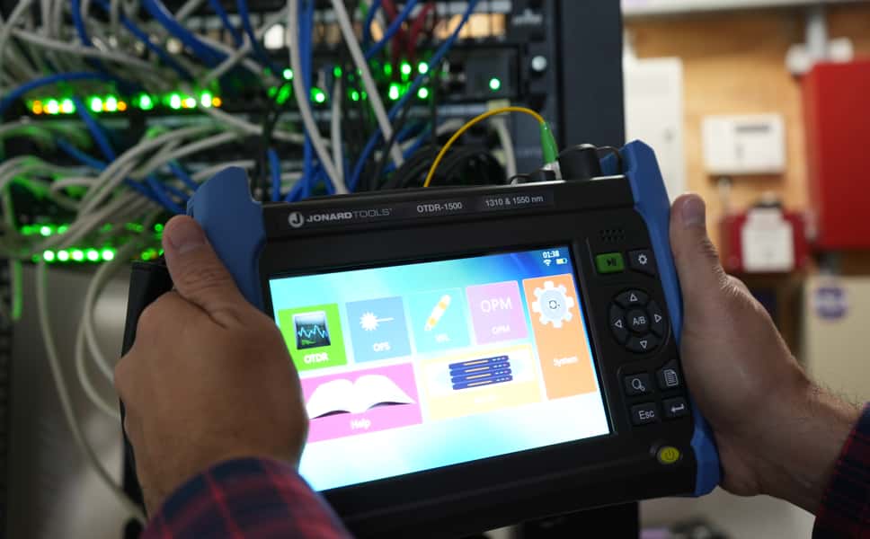
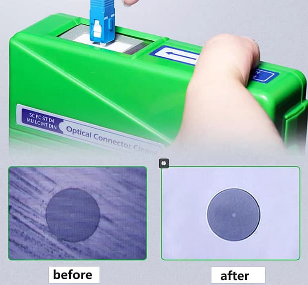
An optical power meter is the primary tool for accurately measuring the optical power of the light signal that is transmitted through your fiber link. When using the meter, always start by powering it on and setting it to the required wavelength, which is often 1310 nm or 1550 nm, depending on the network. The meters work best when calibrated to the operating wavelength, and to measure accurately, you’ll want to prepare a good connection with the cleanliness of the connector! Dust, oil, or dirt on the connectors can cause drastically inaccurate readings of the light signal and degrade the optical signal. Make sure to clean the connectors as best as possible using fiber cleaning kits or lint-free wipes and isopropyl alcohol.
The power meter is configured inline in the transmission path; the fiber from the transmitter is connected to the meter input, then the output of the meter is connected to the receiver. This configuration allows you to measure the actual power transmitted without interrupting the signal path.
To calculate the required attenuation, use the formula:
Attenuation (dB) = P_TX – P_RX_REQ
Where P_TX is the optical power generated by the transmitter and P_RX_REQ is the power (in dBm) that the receiver will tolerate; let’s say the transmitter generates +5 dBm of optical power, and the receiver will tolerate anything between -10 dBm and -20 dBm. To maintain safe operation and not exceed -10 dBm, we would need to reduce the power from the transmitter by 15 dB; therefore, a 15 dB attenuator would be appropriate to reduce the power to -10 dBm, as this measurement means the signal will operate in a safe range, not damage the receiver, and still provide a good signal.
Guessing is removed with precise measurements; the removal of guesswork eliminates waste and damage and dramatically increases reliability in any network.
Step 2: Fixed or Variable? The Decision-Maker’s Checklist
The decision to utilize a fixed or variable fiber optic attenuator is largely dictated by the need for a stable network or the desire for operational flexibility.
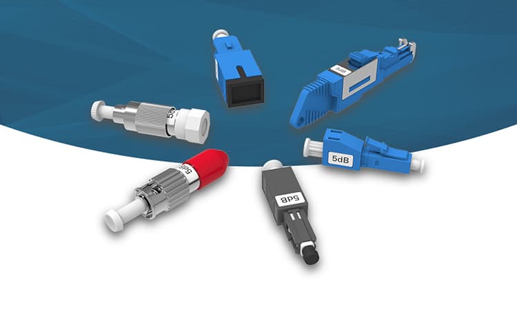
Fixed attenuation provides signal loss at a set, predetermined value, which generally ranges from 1 dB to 30 dB, and will not allow any adjustment thereafter. Fixed devices are great for getting consistent levels of optical attenuation in a stable optical network. A long-haul single-mode fiber link or balanced multi-channel system will greatly benefit from a cost-effective fixed attenuator because of its simplicity, reliability, and stability. The physical characteristics of fixed devices offer the best simplicity and reliability, as there are fewer points of failure, as well as reducing the potential for problems with users setting the attenuation levels prior to deployment.
Variable attenuation allows user-definable signal attenuation. Variable attenuation usually has the defined range of 0 dB to 60 dB and allows the operator to adjust attenuation at any point to accommodate temporary or permanent operational requirements. A typical environment may benefit from variable attenuation at any point where the optical power may vary. Single variable devices may be used in lieu of several fixed attenuators, improving inventory management and deployment speed in the field. The downside will be increased complexity, which translates to a slightly greater insertion loss (even if marginal) and possibly a significantly greater purchase price.
Below is a straightforward guide to making a choice:
- Use fixed devices only in predictable, static networks where minimizing complexity and cost are significantly prioritized. Fixed attenuation is perfect for functional attenuation requirements, such as balancing power among multiple channels or ensuring a receiver only receives signals below a defined optical power threshold.
- Use variable devices in dynamic networks where wavelength tuning and/or variation of the signal level is expected. Variable attenuation will be required in a laboratory setting, test environments, or for maintenance/diagnostic applications.
From a practical standpoint, a variable laser may be prudent to keep available, even if the overwhelming majority of your deployments consist of fixed attenuators. A variable attenuator provides a good balance of consistent operational metrics, with flexibility should changes be needed.
As a side note to the previous points, using these methods ensures the optimum integrity of the signal, as well as minimizing the potential for problems and damage.
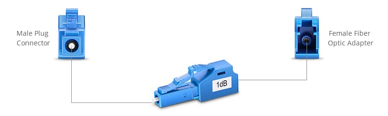
Step 3: Connector Compatibility—Avoid the Costly Mismatches
Alignment among your fiber optic attenuators, fiber type, and connectors is a vital aspect of network health.
For example, your single-mode fiber requires single-mode attenuators, while multimode fiber requires multimode attenuators. Using a single-mode attenuator on multimode fiber or vice versa will create excessive amounts of attenuation, increase your signal loss, and potentially lead to an unstable connection. Without the appropriate attenuation, signal degradation can push network performance under acceptable levels, leading to colorful screens and errors.
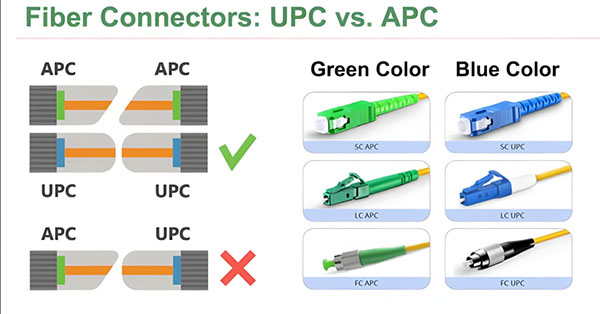
A frequent and overlooked monkey wrench would be the differences in APC (Angled Physical Contact) over UPC (Ultra Physical Contact) polished connectors. An APC connector has the fiber tip polished at an approximately 8-degree angle, which is done to minimize back reflections. Conversely, while a UPC connector is polished flat to reduce insertion loss, it will reflect more light.
When you mix APC and UPC connectors, you can have severe return loss as a significant portion of the optical signal reflects back into the light source. This reflected light can disrupt the quality of the transmission and can damage lasers and receivers. You can understand return loss as a microphone that is susceptible to echoes that deform the voice clarity emitted from the speaker. In the case of the optical system, the return loss will degrade the fidelity of the communication taking place.
The visual differences can help at a glance. APC connectors will typically be located in a green housing, while UPC will be located in a blue housing. Finding and knowing the preferred color can help you identify a problematic connector combination quickly.
In addition to types of polish, you will want to be aware that common connectors such as LC, SC, and ST are also designed distinctly and in different sizes. Usually, an LC connector is preferred in high-density applications with limited space; SC connectors are the simple push-pull connectors, especially for telecommunications networks, while ST connectors are the bayonet locking mechanism typically used in campus or legacy networks.
It will matter that the interface with the fiber optic attenuator and patch cables match correctly to minimize unnecessary wear on the connector and prevent unnecessary signal loss. If you continuously have loads that are not matching, you are potentially increasing the insertion losses as well as putting the connector at risk of damage with each connection.
In summary, making an effort to match connectors will help maintain better signal strength, prevent failure of devices, and help with the service life of the network.
Step 4: Installation & Verification: The Final, Critical Steps
The quality of installation will determine the level of performance and reliability of fiber optic attenuators.
To begin any installation, clean or make sure the fiber connectors and the end of the attenuator are clean. This is simply because microscopic dirt, such as dust or fingerprints, will likely create significant signal attenuation. Use the proper cleaning tools (fiber cleaning sticks or clean lint-free wipes dampened with isopropyl alcohol). Clean connections are critical for signal loss mitigation and stability in a system.
Next, insert the attenuator firmly into the receive port. You will feel a soft click or some resistance to confirm that the attenuator is mated properly. Do not force connectors, as this will surely damage the connector or even the component.
Next, connect the fiber patch cable to the opposite side of the attenuator. Ensure that the fiber patch cable or fiber is not under any strain or sharp bends on its way into the receiver. Any sharp bends or strain points will influence your signal transmission or damage fibers.
Once you have completed the installation, connect an optical power meter to test the optical power on the other side of the attenuator. This will confirm that the signal arriving at the receiver is well within the limits. This confirmation also verifies that the fiber optic attenuator will operate as it was designed, taking energy over power and not overloading the data link.
At the very least, documenting all measured values will help with troubleshooting and performance data gathering the next time any issue arises. Connecting regularly will assist with a preventive maintenance program, reducing downtime and supporting network longevity.
In conclusion, thorough cleaning, installation verification, and systematic optical power measurements will lead to the successful deployment of attenuation with maximum success while keeping transmission integrity and ensuring the long equipment life.
Conclusion
Specific details of selecting and installing a fiber optic attenuator include: start with measured optical power values; select a fixed or variable device that will accommodate changes in the network; install and align connectors properly; and follow an exhaustive installation and verification process.
Following these procedures will help maximize balanced optical signals, minimize damage to devices that are sensitive to power fluctuations (such as the receiver in use), all while improving network stability and eliminating guesswork for power management.
To maintain any high-performance optical system line, it is critical to design and operate a signal attenuation methodology.