A Guide to Choosing Between SFP+ and QSFP+: Avoiding Compatibility Issues
While upgrading network speed from 10G to 40G is an interesting option for performance improvement, there are some hurdles to consider. An operator may find themselves puzzled when weighing the options of SFP+ vs QSFP+ modules because a compatibility error or a few minutes of downtime can be an expensive mistake.Common mistakes such as mismatched modules, connectors, or failing to read the details of the equipment will lead to aggravating disruption and expenses, and must be avoided.It is critical to understand the technical differences of the modules as well as the considerations that must be taken with deployment. An informed choice from the outset will enable the network operator to scale and invest in their infrastructure with confidence.
The difference between the optic modules can impact everything from hardware compatibility to ongoing maintenance costs years later.This introduction is the transition to a practical way to guide the reader through the SFP+ versus QSFP+ dilemma. Each section will provide the reader with actionable information to help determine optimal use cases, where to check for compatibility, and what the cost of running and maintaining one over the other would be.With these factors in mind, selecting and deploying the right solution becomes an easy, straightforward next step that reduces risk to the organization and improves network performance.
What Are the Technical Differences Between SFP+ and QSFP+ Optical Modules?
Delving into the technical specifics of SFP+ and QSFP+ optical modules, there are some important differences that are relevant to network design. In short, while SFP+ can send data at a speed of 10G per port per lane (with a single data lane), QSFP+ is composed of four lanes of data running in parallel to achieve throughput of 40G.SFP+ is like a single-lane highway sending data at 10 gigabits per second, and QSFP+, with those four lanes, is like an expressway that can send four times that speed.
Lane Structure and Data Rate
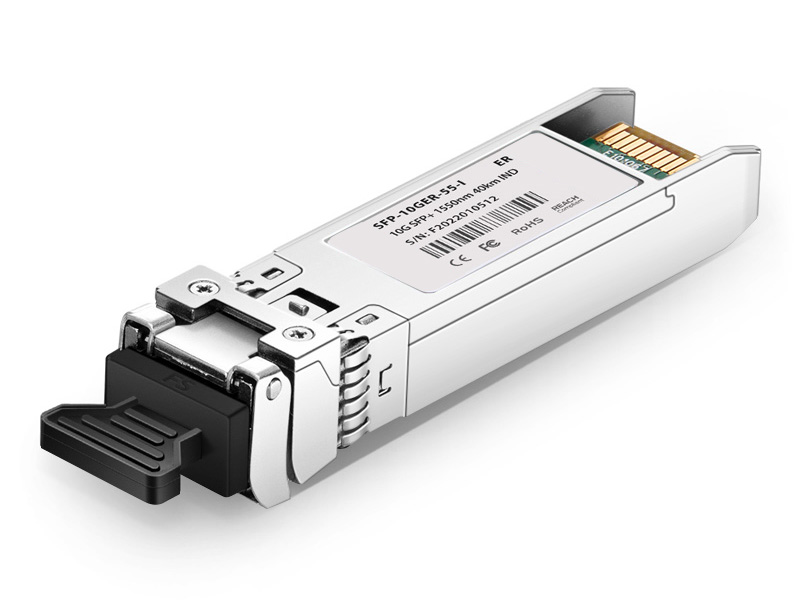
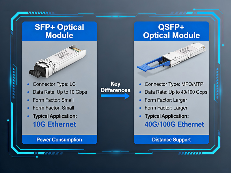
SFP+ modules send data over a single lane of up to 10 Gbps; therefore, SFP+ is well suited for basic, point-to-point connections such as a server-to-switch link. QSFP+ modules, on the other hand, include four lanes of data, 10G each, supported simultaneously.Each lane can operate in parallel, for an aggregate of 40G. This configuration is well suited for connections at the edge or aggregation layer, where port density and high throughput are required.
Optical Components: VCSEL vs DFB Lasers
Among the possible laser types built into the two different modules is the option to choose one that explains the different performance limits of the two modules. SFP+ modules usually use VCSEL, or Vertical-Cavity Surface-Emitting Laser.VCSEL performs well in short-range transport options with low cost and low power consumption. VCSELs operate like flashlights that illuminate a room but only for relatively short distances, which is a cost-effective, sensible option for shorter runs of 10G Ethernet.
Optical Components: VCSEL vs DFB Lasers
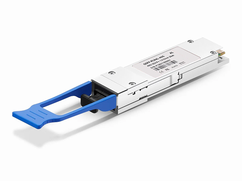
QSFP+ modules commonly use DFB, or Distributed Feedback lasers, which stabilize a coherent beam at longer distances and support the high data rate that QSFP+ is designed for (40G).DFB lasers are narrow like laser pointers and stable, offering directional precision to extend the performance limits of the laser beyond short-haul links.
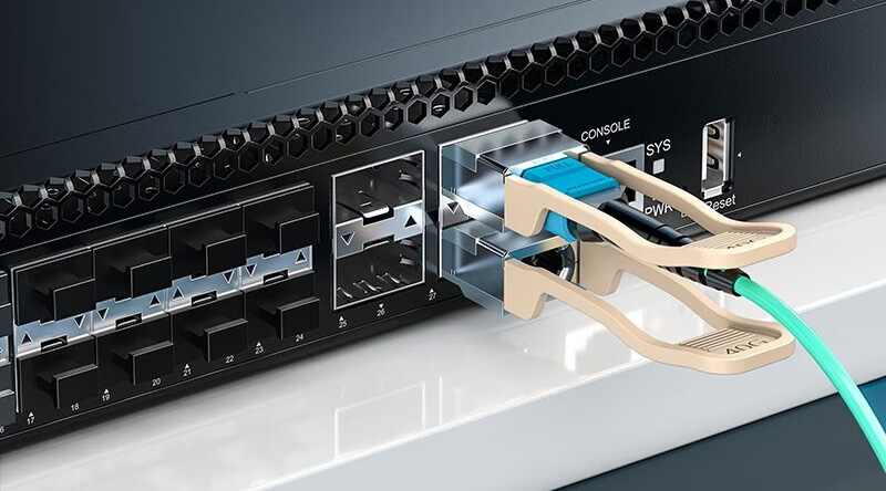
Connector Types: LC vs MPO
SFP+ and QSFP+ also have different physical connectors driven by their lanes. SFP+ typically uses LC connectors that are easy to deal with and intended for transmission of one lane of information over a single fiber patch.LC connectors are very similar to standard power plugs–very small and easy to handle.
Connector Types: LC vs MPO
QSFP+ modules use MPO (Multi-Fiber Push-On) connectors that can handle multiple fiber strands at the same time. MPO connectors are advantageous because they can connect four lanes at the same time in a single duplex cable, which increases port density and is helpful because it simplifies cabling in a high-speed cabling environment.Think of an MPO as like a multi-pin socket powering multiple devices from a single connection.
Architectural Implications
The differences in design can lead to different decisions when considering the architecture of the network. SFP+ is great for simplicity and typically lower power – perfect for access layer links where you may need 10G but do not need to connect more than a few individual servers or devices.Alternatively, QSFP+ works best in environments needing to aggregate capacity and manage efficiency of space – data center spine switches, typically.
Summary Table: Key Technical Differences
| Feature | SFP+ | QSFP+ |
| Data Lanes | Single lane (10G) | Four lanes parallel (40G) |
| Laser Type | VCSEL (short-range focus) | DFB Laser (longer distance) |
| Connector Type | LC connector | MPO connector |
| Ideal Usage | Server-switch, access layer | Aggregation, backbone |
| Power Consumption | Lower | Higher |
Avoiding Misconceptions
A superficial understanding usually fails to recognize that a QSFP+ is more than just a faster SFP+. The four lanes introduce a degree of complexity regarding cooling and signal quality, meaning the hardware must accommodate distinct requirements.In addition, typical SFP+ modules will not usually scale beyond 10G; running them in higher-speed applications creates bottlenecks in the network.Understanding these differences in optical transceivers is vital to avoid incompatibility problems. Failing to understand lane counts or connector types can introduce issues contributing to reduced performance, additional costs, and potential maintenance problems.This level of understanding puts you in a position to ask the right questions to develop the components to match the operational module requirements with the appropriate network expectations.
Why Does Network Architecture Require Different Roles for SFP+ and QSFP+ Modules?
The purpose of SFP+ and QSFP+ modules, within any potential design and network architecture, is explained by each of their respective positions and placement in said design.Each module serves a different purpose as a result of the physical shape and size, capacity intended, and locations within the network.Understanding the purposes or roles within the intended design will help ascertain the optimal selection, larger port density, or exponential performance at the switches.
SFP+: Access Layer Workhorse
SFP+ modules are ideal for access layers where servers connect to switches. These connections are generally 10G connections and match the single-lane 10G throughput capabilities of SFP+. Within this context, the SFP+ is similar to local street traffic pathways providing traffic to your house–it is good and more than enough for a single pathway. Access layer connections require multiple ports to connect multiple servers together, so space and power efficiency come into play. SFP+ modules take less switch real estate per port and can support a higher port count while managing costs. Additionally, the SFP+ design is a simpler design and generates less overall heat compared to higher-capacity transceivers, which can help reduce the total rack density of servers.
QSFP+: Aggregation and Backbone Power
QSFP+ modules are designed for the aggregation and backbone layers of the network, where multiple data streams are converging. At this point in the network, you are dealing with a delivery method that will support greater throughput. In this case, it is 40G. QSFP+ modules operate similarly to multi-lane highways and can carry large amounts of traffic, almost like there are four lanes of traffic moving between switches. When it comes to backbone switches, network architects often select a QSFP+ module to carry four 10G lanes over a single 40G port. Utilizing a QSFP+ module yields a new layer of bandwidth without requiring four times the physical ports, and optimizes not only the space and management of the cabling but also the cost and power consumption on the switch. The switch’s “QSFP+” designation highlights the enhanced thermal and power design of the QSFP+ switch; these modules simply consume more electrical power to operate four lanes in parallel.
Impact on Port Density and Switch Selection
The variation in lane count affects port density in different ways. SFP+ will allow for larger numbers of 10G ports to be contained in smaller switching devices, whereas QSFP+ will aggregate many smaller-density ports into fewer but higher-density ports.This will allow for reduced cabling, simplified patch panel management, and less operational work.SFP+-based switches are designed for relatively large 10G ports at the edge of the network, which simply means accommodating a lot of low-latency connectivity to many individual devices. On the other hand, QSFP+ switches will be used for the backbone role and will have fewer ports for 40G speed and capacity.Balancing the requirements of connectivity is needed when deciding on the switch form factor that keeps the network both scalable and efficient in operation.
Simplified Comparison
| Aspect | SFP+ | QSFP+ |
| Typical Use | Access Layer (server-switch) | Aggregation/Backbone (switch-switch) |
| Data Rate per Port | 10G | 40G (4x10G lanes) |
| Port Density Goal | High (many 10G ports) | Moderate (fewer 40G ports) |
| Switch Design Focus | High port count, low power | High bandwidth, thermal management |
Linking Module Choice to Strategy
Choosing between SFP+ and QSFP+ should depend on your network’s traffic goals and requirements.SFP+ is a good solution for connecting many endpoints that use a moderate amount of network bandwidth.In contrast, when your infrastructure calls for multiple aggregated links with high-speed throughput, QSFP+ is a scalable option to support high-speed throughput and provide port efficiency.This strategic decision avoids either over-provisioning and displacing costs to your network or creating a bottleneck. Both will result in a lower total cost of ownership, and resilient and future-proof layers in your network.
How to Verify Switch and Module Compatibility to Avoid Costly Mistakes?
Verifying that switches and optical modules are compatible beforehand will make your life easier and usually save costly downtime! Having a structured verification and assurance process will help you minimize execution errors and give you confidence in your deployment.
Step 1: Consult Switch Datasheets
This process starts with the switch’s official datasheet or technical user guide. These documents will describe the officially supported types of modules and standards.You will need to determine the types of transceivers supported, such as SFP or SFP+, and the protocols, such as 10G 802.3ae, that are relevant.Using the example of an SFP+ 10G switch, the datasheet will likely specify SFP+ modules that are compatible with the switch, in terms of the module’s wavelength and the associated laser type, etc.This cross-referencing process is useful so that you don’t accidentally plug in an unsupported module.
Step 2: Use Vendor Compatibility Matrices
Numerous switch vendors will publish compatibility matrices. These detailed charts prominently display which approved modules will go with which switch model and the published firmware version.They are like a compatibility “map,” as it gives confirmation that only certified compatible modules will be used.This is an important step to ensure we have no unexpected issues with the wrong hardware or optics, for example, QSFP 40G LR4 mismatch issues with incompatible optics and hardware.
Step 3: Decode MSA and Vendor Codes
Most optical modules are standardized by Multi-Source Agreements (MSA) using identifier codes. The vendor-specific codes are stored in the EEPROM inside each module and are read by the switch firmware during the module’s insertion process.These encoded identifiers can be verified for interoperability purposes. When the codes do not match what is expected or the codes are counterfeit, an error will occur, or the optical module will not link.
Common Causes for “Module Not Recognized”
- Use of unverified third-party modules: Switches may block modules that are not certified.
- Mismatched switch firmware: If your switch is not running the latest version of firmware, the switch may not support newer module types.
- Mismatched electrical or optical specifications: An error will occur if your module has one or more incompatible laser wavelengths or connectors.
- Dirty connectors or broken fiber: There can be conditions where a fiber optic connector looks good and has the proper specifications but is not recognized by the switch, possibly due to dirt or damage to the connection.
Troubleshooting Tips
- Conduct a clean inspection of the fiber and cables of the connectors and module interfaces before installation.
- To ensure module support is up to date, make sure the switch firmware is upgraded on a regular basis.
- If possible, test modules that are suspected to be faulty on known good switches to confirm the suspected faults are legitimate.
- Issue specific switch commands (e.g., show interface transceiver on switches) to check for the expected outputs.
- Maintain a spare pool of certified modules to replace suspected faulty modules and quickly establish if it is, in fact, a hardware failure.
Practical Example
A network operator faces frequent disconnections as a consequence of a QSFP 40G LR4 mismatch.Upon investigation of the switch logs, it was revealed the modules were provided through a third-party vendor and were not certified by any vendor.Once a certified module was installed, the interoperability issue was resolved, providing a stable backbone connection.Using this explicit compatibility checklist will help minimize downtime for module-SFP+ 10G switch compatibility issues or QSFP module mismatches.
What Are Effective Ways to Connect 10G SFP+ and 40G QSFP+ Modules in Mixed Environments?
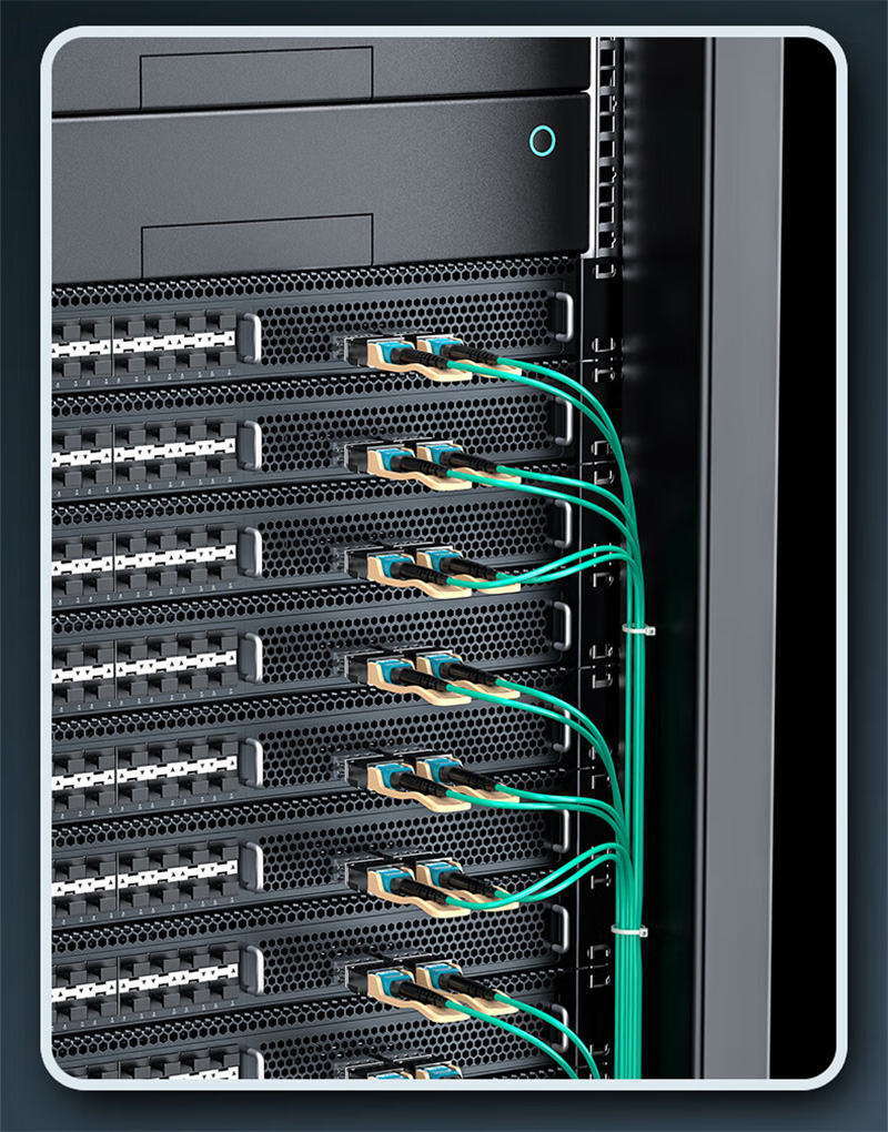
Establishing connectivity with 10G SFP+ modules and 40G QSFP+ modules in diverse networking environments will necessitate pragmatic hardware solutions to ensure compatibility and performance.Two primary options exist to meet this challenge: 4x10G breakout cables and Wavelength Division Multiplexing (WDM) solutions.
4x10G Breakout Cables
Breakout cables take a single 40G QSFP+ port and break it into four separate 10G SFP+ connections. Think of this like a highway splitting into four lanes, with each lane carrying traffic independently.This is ideal for short-distance applications, particularly in data centers, and is simple and cost-effective.The advantages of breakout cables are the relative ease of deployment and management, but they do have distance limitations. Breakout copper cables have a length of up to 7 meters, while breakout fiber distance is typically around 100 meters from the switch.Breakout cables also require the switch ports to be breakout capable and function properly.
WDM Solutions for Longer Distances
For connecting devices over longer distances, WDM technology provides a flexible option. Wavelength division multiplexing (WDM) uses multiple wavelengths of light, combining them into a single fiber.For example, 40G QSFP+ modules can take four 10G signals and send them in parallel over one fiber strand. In this aspect, WDM is similar to a prism, which takes visible sunlight and splits it into the different colors that travel together without interfering with one another.Although it may be costlier to deploy WDM, it can achieve longer distances, sometimes up to several kilometers, while minimizing fiber plant complexity.Any perceived increase in cost or complexity associated with WDM components must be evaluated against network design requirements as well as related budgets.
Deployment Scenarios and Cost Considerations
- Data Center Access Layer: Short runs between servers and switches will often use breakout cables to reduce costs and improve ease of deployment.
- Enterprise Backbone: Longer runs between switches for aggregation can often use WDM setups with an understanding of the financially supported startup cost.
- Cost: Breakouts are often cheaper upfront but come with distance limitations. WDM will require a higher initial cost, as well as a reduced number of fibers, but allows for greater growth of the network in the future.
Summary
| Solution | Distance Range | Cost Impact | Best Use Case |
| 4x10G Breakout Cable | Up to ~100 meters | Low to Moderate | Short-distance data center links |
| WDM Solution | Several kilometers | Higher | Long-distance aggregation/backbone |
Ultimately, the right connection strategy between SFP+ and QSFP+ modules will depend on the deployment requirements and budget restrictions.Often, a combination of methods will provide the best compromise in a complex network.
How to Calculate Total Cost of Ownership (TCO) Comparing SFP+ and QSFP+ Solutions?
The total cost of ownership (TCO) of SFP+ and QSFP+ solutions is more than just a comparison of what the modules are purchased for. It takes a total evaluation of module price, cable price, power usage, port density, and maintenance requirements.All of these factors affect the TCO of the network’s bottom line and total efficiency in terms of long-term sustainability.
Module and Cable Costs
SFP+ modules and their cables usually have a lower first cost. 10G transceivers are inexpensive because they are standardized and made in high quantities.The QSFP+ module will carry a higher price due to its more complicated design, which allows four parallel lanes to carry 40G speeds.QSFP+ also requires a different cable, whether it is an MPO connector or a QSFP+ breakout cable, which will also incur costs.
Power Consumption
Energy consumption has a direct impact on operational costs and cooling needs. SFP+ modules typically consume less energy compared to QSFP+; therefore, they are appealing for high-density access layer deployments constrained by power.This is because QSFP+ modules take advantage of four parallel lanes, being four times (i.e., 4x) the total power use compared to SFP+ modules.Consequently, the cooling infrastructure needs to be designed to cool these higher heat outputs associated with the power output to ensure reliable performance during varying operational stages.
Port Density and Switch Costs
Compared to QSFP+, you’ll need more physical switch ports for SFP+ solutions to achieve the same amount of bandwidth. This has implications on the cost, physical space occupied, and management complexity of the switch.QSFP+ transceivers optimize bandwidth, requiring fewer physical ports. Yes, switches using QSFP+ modules may be more expensive, but in some cases, the savings in cost, space, cables, and management can overcome the added cost.
Maintenance Complexity
When you have a number of SFP+ connections, you will be dealing with more cables and connectors, and more potential failure points. This adds to the complexity of managing the operation for your network teams.Using a QSFP+ can simplify this and aggregate lanes, reducing the number of cables needed and making the patch panel layout easier to manage.However, troubleshooting QSFP+ modules may require a little more technical expertise because of the complexity of parallel lanes.
Summary Comparison Table
| Cost Factor | SFP+ (10G) | QSFP+ (40G) |
| Module & Cable Cost | Lower upfront cost | Higher upfront cost |
| Power Consumption | Lower (per port) | Higher (4 lanes combined) |
| Port Density | Requires more ports | Higher bandwidth per port |
| Switch Cost | Moderate, many ports | Potentially higher, fewer ports |
| Maintenance | More cables & complexity | Fewer cables, complex lanes |
Data-Driven Decisions
Determining whether the best choice is SFP+ or QSFP+ revolves around weighing the cost related to starting up with these options against the costs you’ll see in the years to come.Higher port counts and power restrictions will drive some to SFP+. On the other hand, QSFP+ solutions are space-efficient and provide a bandwidth combination that can result in savings, particularly in denser networks or in the backbone of a network.Assessing network load, plans to grow, and the budget will help you capitalize on good decisions to mitigate the potential for total ownership cost.
What Are Common Deployment Pitfalls with SFP+ and QSFP+ Modules, and How to Avoid Them?
Implementing SFP+ and QSFP+ modules can be simple; however, many pitfalls commonly arise and disrupt network operations with costly implications.In fact, as it goes with many of these types of networks, fiber mismatch, distance bias, and connectors (especially MPO connectors used in QSFP+ modules) are a common problem.
Costly Fiber Mismatch
After the upgrade to QSFP 40G LR4 modules, the data center was intermittently losing the links.After a thorough investigation, it was discovered that the type of fiber in use was not compatible with the use of these new modules. Single-mode fibers were unintentionally replaced with multimode fibers.This mismatch introduced signal loss, which caused intermittent connections and downtime.Identifying the issue led to replacing the use of multimode fiber with appropriate single-mode cables. The replacement resolved the issue.It is paramount to address the need to match fiber types to the types of modules being used.
Common Deployment Pitfalls
- Fiber Type Mismatches: When using incorrect fiber types or mixtures, fiber optic signals can be impeded, resulting in link failures. Several SFP+ and QSFP+ modules are designed to be used with specific fiber standards and must match.
- Distance Failures: Any distance beyond the supported transmission distance will lead to weak signals and dropped links, especially for QSFP 40G LR4 modules. Always confirm the module’s distance capability before deployment.
- MPO Connector Problems: MPO connectors do a good job of simplifying cabling but may cause trouble when not handled properly. Some common problems can stem from poor alignment, dirt, or damaged pins. Unlike the simpler LC connectors used with SFP+, MPO connectors require more careful handling and cleaning.
- Uncertified Module Installation: Installing third-party modules, or even modules that were not certified, will commonly cause errors with module recognition or impaired performance.
Pre-Deployment Checklist
- Confirm Fiber Type: Ensure the type of fiber (single-mode or multimode) matches the requirements of the module.
- Confirm Link Length: The distance of the link should be measured against the range ratings of the module so that weak signals are avoided.
- Check Connectors: Look at the MPO or LC connectors and inspect for dirt, damage, or misalignment.
- Confirm Module Compatibility with Switch: Cross-check approved modules against a datasheet for the switch or a compatibility matrix from the vendor.
- Ensure Firmware is Updated: Ensure that the current firmware of the switch supports the installed type of module.
- Check the Links Independently: Before putting the link into full service, validate the link using an optical power meter or the built-in link diagnostics test.
Preventive Practices
Using this checklist as part of your deployment procedure should minimize some of the more common mistakes when installing SFP+ and QSFP+ transceivers, but care should be taken around MPO connector formats and handling them properly with cleaning kits and caps.Have network engineers regularly verify firmware versions and compatibility lists with various fiber-optic transceivers.Doing this will prevent the installation of transceivers you eventually need to troubleshoot at your expense and time, and also help with the stability of the link.
Why Are Thermal and Signal Management Critical in QSFP+ 40G LR4 Deployments?
QSFP+ 40G LR4 modules contain four parallel lanes for data transmission that operate at high speed. This design introduces some unique thermal and signaling issues that could affect module reliability and network stability.
Heat Generation Challenges
More lanes mean more lasers and more electronics operating together at the same time, introducing more heat than a single-lane module like SFP+. You can think of it like a few engines running together in a small enclosure. Without cooling, the temperature increases rapidly.An excessive amount of active heat can lead to damaging components and degrade overall module reliability.
Signal Integrity Concerns
To ensure signal quality across four parallel lanes requires precise synchronization. Heat variations or electrical noise can distort signals or create interference and crosstalk that disrupt signal performance.Ensuring strong signal integrity takes more than just optics; it also requires thermal stability to keep performance stable.
Cooling Practices
It is vital to implement adequate cooling for QSFP+ 40G LR4 deployments. Network equipment should incorporate airflow designs that dissipate heat through an airflow path around the modules.Heat sinks or fans located in proximity to the transceiver cages can add to the overall thermal management. Adequate ventilation in the rack helps reduce hot spots, which can accelerate the wear and tear of the modules in the rack.
Proactive Monitoring with DDM
DDM (Digital Diagnostic Monitoring) technology provides live metrics on the health and status of a transceiver module, including temperature, voltage, and laser bias current.Monitoring these metrics, where possible, can alert users to developing thermal or signal problems before the module fails completely.Automated alerts and diagnostics assistance will help put you in a proactive maintenance state and minimize downtime.
Key Takeaways
- QSFP+ modules consume considerable power, causing them to create more heat, requiring them to be cooled efficiently.
- Providing signal integrity mandates consistent operational temperature across the entire parallel lane.
- Implementing DDM in your cooling practices improves reliability and increases the usability of the module.
- Without a thermal management approach, there is an increased risk of failure, leading to perpetual downtime and unexpected replacements.
Keeping in mind all these advanced considerations will justify the investment in QSFP+ 40G LR4 modules capable of high-speed network provisioning with assured stability and durability.
How to Use Diagnostics and Troubleshooting Techniques to Ensure Stable SFP+ and QSFP+ Links?
SFP+ and QSFP+ links are critical to stable and reliable network connectivity so proper diagnostics and troubleshooting techniques are crucial. Identifying problems as quickly as possible reduces downtime for the business, providing a stable network experience.
Step 1: Check Digital Diagnostic Monitoring (DDM)
We typically start with checking DDM diagnostics. This allows us to gather real-time health data to check temperature, voltage, and optical power levels.If any of the diagnostic readings are outside expected parameters, it is typically an indication of overheating, power problems or degraded signal that will affect the stability of the link.
Step 2: Physical Troubleshooting
Next, it is time to do some physical troubleshooting. Inspecting the physical components, such as the fiber connectors and cables, for dirt, damage or misalignment are key.It is important to note that even a few specks of dust can degrade the signal enough to potentially take your QSFP+ 40G LR4 modules offline. If the optics are not working as intended, cleaning and reseating the cables usually fixes the unrecognized module or link drop situation.
Step 3: Lights and Link Indicators
The status lights on a switch can tell you many things visually about what is going on with the link.Flickering lights or devices that are amber or off generally indicate a physical or configuration problem.
Step 4: Checking Optical Power Levels
Possibly number four, you will need to measure the optical power levels. Here you will color and check that the transmitted and received power are within the spec for the module.A faulty optic or too great a distance are usually to blame for weak signals if they are more than a little light apart.
Common Issues with QSFP+ 40G
QSFP+ modules have their unique problems to contend with notably crosstalk rejection and signal integrity issues across their parallel lanes.The great majority of these mode drop events will be linked to power instability and contamination in the connection. You can avoid most of these problems by regularly checking your DDM and being proactive about cleaning connectors.
Practical Implementation for Troubleshooting
- Check to see the DDM status is abnormal.
- Inspect and clean any connectors.
- Verify you are using the proper cable types and cable lengths.
- Test optical power with your power meters to check distance.
- Swap any suspected faulty optics with optics that you know are good.
- If it still doesn’t recognize the module try an updated version of the firmware on the switch itself.
- Check with vendor compatibility lists to check for any known issue that doesn’t warrant to be in you system.
Supporting Network Engineers
This structured approach helps break down troubleshooting a complex problem into manageable steps.By constantly monitoring the health of the optical transceiver and doing simple physical inspections, they can fix the problem quicker to make the SFP+ and QSFP+ links more reliable and efficient.
How to Plan Your Network Investment for Future Scalability Beyond 40G?
When planning network investments, it is advised to plan with the flexibility of scalability beyond 40G to avoid technology obsolescence. Thinking about growth in the future will allow for a cost-efficient and seamless transition.
Upgrade Paths: QSFP+ 40G to QSFP28 100G and QSFP-DD 400G
The QSFP28 modules build upon the QSFP+ form factor and increase speeds to 100G by increasing lane data rates from 10G to 25G.This is useful in higher bandwidth networks that need to go faster without having to change out the hardware entirely.Then on top of that, the next development is QSFP-DD (Double Density), which scales throughput even further to 400G by providing more lanes and electrical contacts.To visualize this better, we should conceptualize QSFP+ as a four-lane highway where the maximum speed is 40G, QSFP28 is an upgraded expressway that is able to handle 100G traffic with each lane being able to accept a faster speed limit, and QSFP-DD is like a multi-lane superhighway that is capable of increasing broadband limits even more.
Modular Switches
Today’s switches typically support backward compatibility, which allows them to accept both QSFP+ and QSFP28 modules in the same slot, giving organizations several flexible migration paths.This allows organizations to upgrade their ports incrementally, and they do not have to replace the whole switch.Switches today have a modular design allowing organizations to mix their outdated generation transceivers with today’s transceivers; this allows a smooth continuity of operations while moving to the new tech.Subsequently, when an organization needs to add space or optimize power budgets because of increased demands for throughput and density in their networks, modular switches allow organizations to do this while also getting the return on investments they made several years before.
Future Network Designs
- Choose equipment that is compatible with future transceiver standards.
- Choose modular switches that are backward and forward compatible.
- Choose and build out physical infrastructure (fiber/racks) that accommodates future higher speeds and densities.
It’s important to maintain a balance with the organizational needs of today and the ability to upgrade the hardware down the line so equipment will not become obsolete.
Summary Table
| Upgrade Level | Data Rate | Module Type | Migration Benefit |
| Current | 40G | QSFP+ | Baseline for scaling |
| Intermediate | 100G | QSFP28 | Higher speeds without rewiring |
| Advanced | 400G | QSFP-DD | Massive bandwidth, future-proof |
Integrating QSFP+, QSFP28, and QSFP-DD for future-proofing interfaces ensures scalable network expansion and investment protection.Viewing network design decisions through this lens will help ensure both performance and longevity.
Conclusion
Balancing many aspects is key to your decision-making process when selecting between SFP+ optical modules and QSFP+ optical modules.Technical fit confirms that the optical module will fit your deployment and bandwidth requirements.Switch compatibility will prevent potential costly errors and downtime.Cost considerations should reflect both the initial investment and long-term ongoing operational costs.The challenges of deployment functionally relate to connector management challenges and thermal management considerations that may compromise reliability.Future-proofing the module ensures your network is structured to scale without premature obsolescence.
Understand that a well-informed decision reflects acceptance of all the features listed above as a commitment to build a robust and efficient network.For instance, consider building a structure that, upon completion, allows you to add components as the need arises.Starting with the appropriate foundational components will aid in facilitating growth upon desired capabilities, with ease and fewer costs.A clear understanding regarding lane structure, connector type, and optical technology should aid in avoiding typical traps.When purchasing components like QSFP+ optical modules, it is helpful to check the specification sheets and conformance matrices on the vendor’s website to specifically identify if a certain optical module is compatible.
Attempting to find potential compatibility post-purchase often results in rejecting the module or an unsuccessful link.Similar assessments may also be utilized to limit maintenance issues on established installations.Future-proofing plans to accommodate 100G with QSFP28 100G or potentially 400G updates with QSFP-DD optical modules will limit non-productive expenditures today.Ultimately, the choice of optical module or optical modules impacts the delivery of network stability and scalability.Planning your model will benefit your network and performance for agility in current and future standards.Using balance will set a trusted network team in a position to build an infrastructure to modify as capacity is added over the growing demands.