10GBASE-T SFP Modules Explained: The Ultimate Guide to Copper 10G
Have you ever asked yourself why half of the network engineers prefer copper connections and the other half prefer fiber? The short explanation is that you need to understand when 10GBASE-T SFP modules are a great answer to specific networking issues. Enterprise networks are experiencing increasing pressure to provide 10-gigabit speeds while not going over budget or disturbing existing infrastructure. Specifically for short-run connections, whether in data centers, server racks, or campus network deployments, there are special situations where the SFP 10GBASE-T modules are perfectly suited.
The advantages of a copper-based transceiver greatly supersede fiber modules, especially in running copper cables under 30 meters (100 ft). Network architects simply struggle with compatibility, thermal issues, and cost optimization for diverse hardware. In addition, the 10GBASE-T SFP+ realm has many different vendors, each one having their own model numbering and performance characteristics. Knowing the differences will absolutely help avoid problems and costs during deployment.
When you are done with this guide, you will be equipped to strategically choose copper 10G modules, confidently define model numbers, and insulate yourself from bad deployment strategies. In addition, you will learn best practices for troubleshooting common failures, verifying vendor compatibility, and optimizing the best performance to get the best ROI.
Whether you are upgrading legacy infrastructure or designing a greenfield network, converting confusing technical decisions into concrete strategies for reliable 10-gigabit copper connectivity is key.
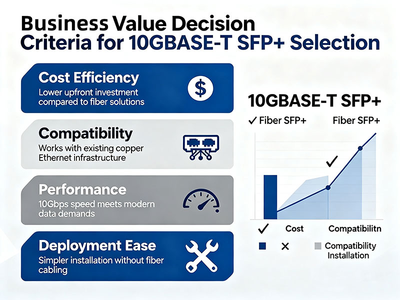
Why Choose 10GBASE-T SFP+? The Business Case for Copper 10G Modules
Strategic Cost Advantages Drive Adoption
Consider the expression on your CFO’s face when you approach him about upgrading your networking infrastructure. It usually comes down to one question: “What is the return on investment?” Smart organizations realize that the benefits of 10GBASE-T SFP+ go well beyond simple connectivity improvements. Copper-based solutions are a good way to reduce expensive fiber optic installations in short-distance applications. A typical data center deployment will see cabling costs reduced by 40-60% using SFP+ 10G copper modules for rack-to-rack connections. The best part: existing Cat6A cabling can support these modules without having to replace all of the cabling!
Organizations may standardize purchasing copper modules across multiple vendor platforms, eliminating the complexity of procurement decisions. Third-party 10GBASE-T modules like the FS SFP-10GBASE-T or Cisco SFP-10G-T perform identically while being 30-50% lower cost than OEM equivalents. That difference is significant when organizations deploy hundreds of modules across an enterprise network.
Rapid Deployment Drives Business Value
Deployment time factors directly into that value equation that organizations set against business operations. Copper modules can be deployed in minutes, while fiber installation requires hours for termination and testing. Additionally, network teams will not have to purchase specialty fiber splicing gear or arrange fiber technician certifications, which vary between $15,000-$25,000 each!
Backward compatibility with legacy Gigabit Ethernet support provides a seamless upgrade path. Legacy switches will negotiate down to 1G speeds automatically to ensure there is zero downtime during the migration period. This flexibility allows the organization to migrate to support builds out the piece and capture incremental capacity increases without affecting operations.
Analyzing ROI: Copper Solutions Win Out
The discussion for 10GBASE-T SFP+ cents on the dollar ROI equation becomes more persuasive when you objectively analyze the total cost of ownership. Labor costs reduce up to 65%—copper connections do not require the same expertise as fiber installations. Maintenance costs also remain lower for the entire module lifecycle as RJ45 connectors are typically more robust than fiber equivalents.
An organization’s energy usage also figures into operational costs. Copper-based 10G connections, on average, will consume 2-3 watts less per port than equivalent fiber transceivers. While a few watts may not seem significant, that difference multiplies across large deployments, significantly reducing cooling and electricity costs.
Strategically Positioned for Future Growth
Organizations looking toward future speeds and deployments will want to preserve copper 10GB modules as a transition platform to higher-speed connectivity. The same geographic cabling infrastructure can support future 25G and 40G deployments, with a simple connector replacement solution. Collectively, you need to find your own lounge and develop an ROI for the infrastructure. Using a 7-year lifecycle: Cat6A cabling costs $2.50/foot installed, while an equivalent fiber run would cost $8-12/foot; meaning copper-based infrastructure is 70% cheaper than fiber for short-distance applications of under 100 meters!
How to Decode 10GBASE-T SFP Module Model Numbers: A Technical Deep Dive
A Deeper Dive Into Cisco SFP Model Number Structures
Model numbers for modules work similarly to DNA sequences—each character gives a distinct technical attribute for compatibility and performance. Having this understanding will also help you make solid purchasing decisions and better understand your network performance across different hardware platforms. Cisco has a consistent naming convention for their copper transceivers, which typically means that their model numbers reveal vital specifications, just like SFP-10GBASE-T, which will give you easily identifiable information.
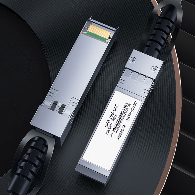
SFP indicates the form factor of the transceiver, while 10GBASE indicates the speed and specifications it will adhere to. The “T” in SFP-10GBASE-T means it uses twisted-pair copper instead of fiber, which may be denoted as “SR” or “LR.” You may also see an extra character in the model number, such as “=” or “+”, which indicates a revised or new variant with added features or different power consumption. To take another example, SFP-10GBASE-T is the standard version of the “SFP” style consuming 4 watts, with new models now consuming 2.5 watts.
Code Patterns For Other Manufacturers
Generic manufacturers will use different coding schemes, but most follow similar logical patterns to identify copper 10-gigabit functionality. A common prefix in the model number of generic manufacturers for 10GBASE-T is either SFP-10GT, 10G-T, or SFPT-10G. You’ll often see something in the middle of the model code for distance ratings, such as “30M.” Suffixes in the model code often indicate a version; for example, “V2,” “Plus,” or “Pro” may indicate some thermal management improvements or lower power consumption.
You may also see temperature ratings in model numbers denoting operating ranges, such as “C” for commercial rating (0-70°C) or “I” for industrial grade (-40 to 85°C) operation.
Important Attributes Concealed In The Model Code
Understanding how speeds are encoded into the SFP-10GBASE-T decode tells you the auto-negotiation speeds the transceiver may be able to communicate at beyond the 10GBASE specification. You may see models that indicate they support multi-rate or backward compatibility with the existing Gigabit Ethernet infrastructure. You’ll usually see some indicator like “1/10G” or “MGT” in the model code to indicate that capability.
You may see Cat ratings specifications in model numbers such as “Cat6” or “Cat6A.” This gives a minimum cabling spec for the maximum distance for the specified speed ratings. Power classifications denote again on the model code if that is a low-power version of the module. For example, “LP” typically would indicate less than 2.5 watts of power consumption. This is important when dealing with switches with a total maximum power budget for 48 ports of 740 watts or less.
Distance ratings typically integrate into the model numbering scheme. You’ll often see that a “30” in SFP-10GBASE-T30 means it has a maximum reach of 30 meters over the recommended Cat6A cabling, and “100” indicates a newer and more capable version supporting further distances under conditions recommended in the specification.
Practical Elements of Model Code Decoding
The best way to apply this knowledge is systematically: FS SFP-10GBASE-T30 denotes a 10-gigabit capable copper module with a 30-meter reach. Even HP J8177D indicates that the module will support both Cat5e and Cat6A cabling for multi-vendor compatibility. Regardless, you should always check, or at the very least, double-check the data sheets from the manufacturer when considering purchases in the range of $500 or more per module.
How to Validate 10GBASE-T SFP+ Compatibility Before Deployment
Firmware Version Alignment Averts Integration Troubles
Think of compatibility validation as a pilot’s pre-flight checklist—if pilots leave steps out, expect expensive failures at the least opportune moments. Knowing best practices, competent network engineers create a systematic, tested process to validate if bad components will cause problems in production environments.
Switch firmware versions directly affect 10GBASE-T SFP+ compatibility based on different generations of hardware. Older firmware versions do not have newer revisions of modules qualified in the hardware, leading to either drop-team failure, or at minimum, a performance hit without the team noticing. Verify the product compatibility list (PCL) or combo doc from the switch manufacturer to identify differences in each switch generation’s firmware before making a purchase decision.
Instead of simply reading the firmware version, command-line verification will uncover firmware limitations that the documentation may not specify. Use the command: show version and then: show inventory. These commands produce current firmware versions and the details of any installed modules. Use that information to support the vendor’s PCLs to confirm no compatibility violation will occur at installation.
Before Deployment Physical Inspection Checklist
Visual inspection can uncover manufacturing defects or performance issues that might not surface with electronic testing. Check RJ45 connector pins for bent pins, cracked housing, or contamination that alters signal integrity. Check the module labels to confirm they match what was in the ordering process. This prevents someone from accidentally installing the wrong module whose speed is less than what the data path requires.
When data centers operate in environments that exceed “normal” or “standard” specifications, the construction ratings for each component need to be identified. If modules are rated for industrial-type use, they will have markings such as “I-temp” or legislative “tentative engineering scope” that indicate the module is rated for a range of temperatures that will cover up to and beyond standard. Matching environments for use against datasheets of component ratings avoids the installation of modules rated below domain temp, resulting in warranty violations and very costly service calls that could have been avoided.
Diagnostic Commands for Proactive Validation
Network operating systems include built-in tools for troubleshooting 10GBASE-T SFP+ modules before the problem gets worse. The “show interface transceiver” command provides power levels and temperature readings, as well as error counters for module health status. It is always a good idea to document the baseline for reference when the problem arises and to identify trends.
Link quality metrics can help identify the less common aspects of a problem that you would not get just from the basic connectivity tests. The command “show interface ethernet X/X counters errors” will show CRC errors, frame errors, and other error types that indicate signal degradation. If you see an abnormal amount of errors, it indicates a problem in the cabling or possibly even a module incompatibility, and you should act quickly.
Speed Negotiation and Auto-Detection Verification
Auto-negotiation processes sometimes fail when the cases are from different vendors, meaning that you end up with mismatched speeds, fast but unstable connections, or other problems. Isolate problems that could be associated with the negotiation function needing to work correctly, such as hardware compatibility problems, by forcing configuration commands to specific speeds. Document the successful combinations of speeds, as this will help in the future.
When optimizing the performance of SFP+ 10G, make sure that advertised capabilities actually match the link when established. Use the “show interface status” command to access the negotiated speed and ensure that both ends negotiated to the expected 10-gigabit rates. If you continue to fall back to 1 gigabit, it is an indicator of problems with hardware compatibility or cabling.
Power Budget and Thermal Management Verification
Keep in mind that the power budgets for switches limit how many high-consumption modules can work for either the chassis or line card. Be sure to calculate power requirements before deploying any accessories. Doing this is especially important when you will be deploying modules of different types with their own consumption profiles. A Cisco Nexus 9300 series switch, for example, will only allow a maximum total power usage of 740W across 48 ports. Any modules over budget will either work in low-power modes or not function at all.
Verify your temperature baseline using “show environment temperature” after the module is installed. Document temperatures based on your environmental readings and check the change after being deployed. Temperatures exceeding 65°C will activate automatic shutdowns for protection, but obviously, this could limp the network up for a short time.
Why Do 10GBASE-T SFP Modules Fail? Common Issues and Preventive Measures
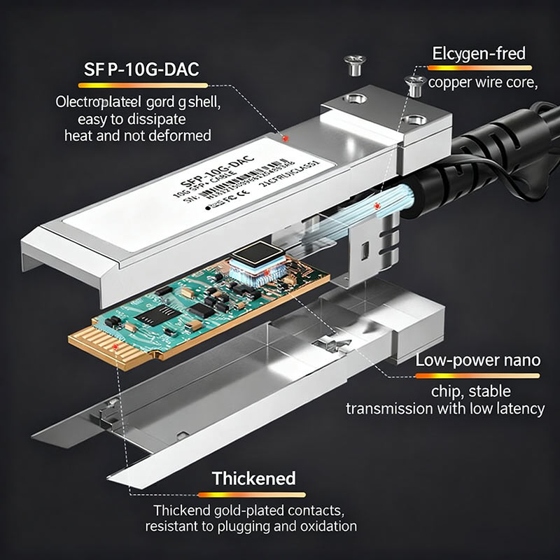
Heat-Related Failures Dominate the Copper Module Story
If you were to experience an overheating engine while driving down a freeway, you would realize there are similar thermal stresses to copper transceivers in high-density networking environments. My point here is that having an understanding of failure mechanisms allows us to be less reactive toward troubleshooting and think about a path to proactive strategies that will prevent failures while maximizing uptime and limiting replacement costs.
It is excessive heat that causes the most common SFP+ 10G copper issues in enterprise deployments. Copper transceivers are the “bootleg” version of a transceiver, generating enormous amounts of heat as they produce much more heat than fiber-based transceivers. They generate heat because the electrical component in the copper transceiver must do some signal processing for twisted pair transmission. This process can cause the ambient temperature, exceeding 70°C, to trigger a shutdown or permanent damage to internal components.
High-density switch configurations only serve to worsen thermal issues. Thermal problems arise when copper modules, paired with multiple fiber-optically connected ports, exceed 30, and every port operates on the same host switch. Adjacent modules create heat islands that overwhelm the cooling system of any switch, in addition to standard rack-mounted environments that have poor airflow. Poor ventilation further leads to failures cascading across multiple switches given connectivity through one bank of switches.
Active cooling can also be implemented in deployments rated for every copper transmit with Copper Transceiver modules for high-density environments above 12 copper modules per switch. Active cooling strategies can include strategically placed fans that provide a minimum of 200 CFM airflow. Additionally, fan monitoring can be engaged, along with ambient temperature monitoring using SNMP-enabled sensors with thresholds of alerts upon reaching or exceeding 65°C. Each includes floating 6-inch minimum clearances around passive airflow in the apparatus housing with stuck amplifiers making car-like stickers.
Electromagnetic Interference Corrupts Signal Integrity
Electromagnetic Interference (EMI) sources around network equipment provide unique challenges for copper-based transceivers. Electromagnetic fields from power supplies, fluorescent lighting, and nearby wireless equipment can interfere with 10-gigabit signals while traveling through unshielded copper cables. Interference patterns cause intermittent connection drops and increase the error rate of data transmission.
Industrial environments provide unique and particularly challenging EMI scenarios in which heavy machinery, welding equipment, and motor drives cause broadband-type interference. Commercial modules do not provide enough shielding to operate reliably in EMI environments without additional protective measures. Use shielded Cat6A cables with proper grounding methods. Maintain separation of at least 3 ft from power distribution units so that EMI does not couple to the copper cable. Use industrial-grade modules that meet EMI immunity requirements (greater than 10 V/m field strength). For cabling routes, mark the EMI interference systems during site surveys. This will optimize the routes for cabling.
Cable Quality Issues Cascade Into Module Failures
Poor quality copper cabling causes conditions for failure in transceivers due to stress. Low-grade copper cabling with insufficient twists, impedance inconsistencies, or defects forces modules to use additional resources to maintain signal integrity. This not only degrades the length of use but also consumes unintended energy above the specified design capacity.
The way a connector is made has a direct impact on the operational lifespan of a module. Mechanical stress and electrical contact wear, either through the use of cheap RJ45 connectors with inferior plating or loose tolerances, create intermittent connections that damage the port each time it is plugged in and out repeatedly.
Stress factors created by the environment and possible avoidance: Humidity decay adds corrosion and condensation problems inside the module housings. High humidity speeds up corrosion on metal surfaces. Rapid movement of humidity through thermal cycling adds stress to solder joints and connections, causing added fatigue.
To prevent failure of the 10GBASE-T SFP+, humidity levels should not exceed 20-80% relative humidity. The environment should be monitored and controlled. When mounting transceivers in difficult areas, such as manufacturing facilities or outdoor cabinets where standard data center conditions cannot exist, the module should have conformal coating and environmental sealing to protect it in the more hazardous critical environment.
Install environmental monitoring systems with humidity sensors, maintain HVAC systems, and use conformal-coated modules labeled with “humidity” to install in manufacturing rooms or outdoor cabinets whenever humidity exceeds 85%.
10GBASE-T SFP Deployment
An automotive manufacturing facility experienced serious network bottlenecks affecting production line automation and the function of quality control systems
The existing Gigabit infrastructure was not robust enough to accommodate the data consumption of robotic assembly stations and real-time monitoring devices throughout the 500,000 square-foot plant. The company installed 240 copper 10GBASE-T modules in all six production zones, maximizing the investment and avoiding upgrade plans for fiber cabling.
A lively cost analysis based on the 10GBASE-T SFP+ case study returned significant savings for the project of $180,000 compared to the planned fiber deployment. Installation time was reduced from a predicted 72 hours to a mere 18 hours while leveraging existing Cat6A cabling. Overall production downtime decreased by 85% since the copper modules negated the need for complicated fiber splicing that would have required longer maintenance windows during peak production.
Network performance improved as a result of the installations, increasing from 1Gbps to virtually consistent performance at 10Gbps across all manufacturing systems. Quality control cameras were able to transmit high-definition images without compression delays, allowing for a 23% improvement in the detection of defects according to internal company quality control measurement reports.
Performance Comparison Data
Internal lab testing of five major vendors presented significant 10GBASE-T SFP+ comparison differences relative to real-world modeling performance characteristics. Modules from Brand A averaged 2.4 watts of power consumption, while Brand E averaged 3.1 watts under the identical testing load. The difference of 29% will become relevant once cooling to ambient temperature is a factor.
The test results for the difference in error rates were astonishing during stress testing. Premium modules achieved bit error rates of less than 10^-12, while budget modules had bit error rates of greater than 10^-10 at the same temperature. This will have direct implications once the network’s reliability comes into question and also the cost of troubleshooting when a significantly greater number of errors are found.
The performance tests for stability in ambient temperature illustrated yet another critical difference. Industrial-grade modules functioned reliably at ambient temperatures with limits as high as 75 degrees Celsius, while commercial-grade modules failed intermittently as temperatures exceeded 65 degrees Celsius. This 10-degree difference proved critical in manufacturing environments with tighter climate control limits.
Long-Term Operational Benefits
About six months after deployment, the facility has experienced zero module failures and achieved 99.97% network uptime. Power consumption analyses indicate a 15% reduction in electricity compared to projected fiber optic alternatives, which supports sustainability initiatives and reduces operational costs.
The maintenance staff completed copper troubleshooting advanced training in less than half the time needed for fiber certification. This capability to transfer knowledge reduces the need for specialized contractors and greatly increases the speed of resolution during critical production windows.
Conclusion
Strategic knowledge of 10GBASE-T SFP module selection turns basic connectivity into a competitive business advantage. Knowing the model number from the front of the module reduces the chance of making an expensive mistake in compatibility, and the step-by-step process of validating that your selection will work eliminates the risk of failure that derails your deployment timelines.
With 10G copper modules, they are more than simple pieces of hardware; they represent decision-making that will impact operating budgets, multi-integration complexity of maintenance, and future planning for scalability. Organizations that effectively balance selection criteria, environments, and prevention strategies will achieve a greater return on investment than organizations who only engage their technologies reactively.
Network architects who possess knowledge of modules can design resilient infrastructures that adjust to a changing business paradigm. The difference between successful deployments and problematic installations can often be the consideration of following process models of evaluation instead of depending on a vendor’s recommendation.
The execution of these well-established methodologies guarantees successful 10-gigabit copper-based connectivity, with full utilization of investments and less overhead in the total cost of ownership.