1.25G SFP Module Application Guide: Pinpointing and Solving Low-Speed Optical Module Needs
Network administrators often face difficult decisions when implementing 1.25G SFP modules in the enterprise space. Legacy infrastructure can have explicit compatibility requirements that add to the confusion when selecting modules. Mixed-speed network topology can factor into deployment strategies, especially when legacy equipment is utilized with newer switching platforms. While cost may drive organizations toward adopting 1G, the technical aspects may be difficult to discern.
Compatibility matrices can quickly become unwieldy when looking at vendor specifications and existing equipment. Distance limitations, wavelength, and connectors add additional layers of complexity to what may be a straightforward purchase. SFP GE T offers a key bridge between legacy technologies and modern network architectures. However, implementation may often be delayed by installation errors, environmental factors, mismatched configurations, troubleshooting, maintenance protocols, long-term reliability of new technology.
At some point, guidance will be required to better optimize 1.25G SFP deployments over various network installations. Practical frameworks will help decision making while minimizing mistakes that can be costly and disruptive. Comprehensive troubleshooting methodologies minimize downtime and streamline overall performance of the network while being cost sensitive.
What Is the Strategic Role of 1.25G SFP Modules?
SFP 1G modules are key players in bridging the gap between aging infrastructure and frugal network vision. Organizations that are operating legacy equipment understand how critical these modules are for allowing some hardware to live longer than a day in the grave. Rather than scrapping entire switching platforms, 1.25G modules can be put in service to preserve capital and continuity of operations. Cost-sensitive environments benefit from the beginning of 1G vs 10G speed advantages. For detailed legacy network compatibility strategies: Read our 1G SFP Legacy Compatibility Guide.
Manufacturing plants, schools, and branch offices often operate within strict budgets and need reliable connectivity but do not require or want to pay for the cost of a higher-speed solution. Another key role for SFP modules is to be deployed in low-bandwidth applications. Voice over IP, building automation networks, and basic internet access will not need increased speeds above 1G. These applications are ideal to accommodate the use of 1.25G SFP in place of 10G, while also not adding additional infrastructure overhead.
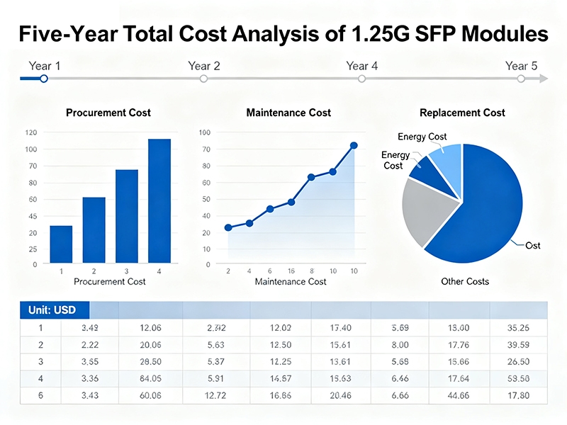
Five-Year Total Cost Analysis:
| Speed Tier | Module Cost | Switch Port | Infrastructure | Power | Total |
| 1.25G | $65 | $150 | $45 | $180 | $440 |
| 10G | $280 | $800 | $120 | $540 | $1,740 |
| 25G | $450 | $1,200 | $180 | $900 | $2,730 |
When comparing the cost of investing, financial benefits start to emerge. A standard 1.25G SFP module will run between $45-75, while the standard 10G option will cost $180-350. The supporting infrastructure, such as the switches and cabling, is 3-4 times the amount of a 1G deployment for a 10G deployment. Nevertheless, there are drawbacks to these strategic advantages.
Distance limitations are capped at 10km for standard single-mode modules compared to 80km for long-reach single-mode modules. Also, in terms of scalability, you can find limitations if your company’s bandwidth requirements increase in the future. SFP GE T benefits, such as power consumption for the port, generally range from 1W, while the 10G port can use anywhere from 3-5W per port.
One of the best case studies for an SFP 1G application can be found in the automotive manufacturing environment. In assembly line production, the requirement to ensure a stable 200-500Mbps for PLC communication and quality monitoring systems must be maintained. Ford’s Dearborn site has utilized 2,400 SFP modules across their production lines, achieving 99.8% uptime over a 12-month period and saving Ford $1.2M compared to using 10G modules, all while achieving less than 10ms response times.
How to Select the Right 1.25G SFP Module for Your Network?
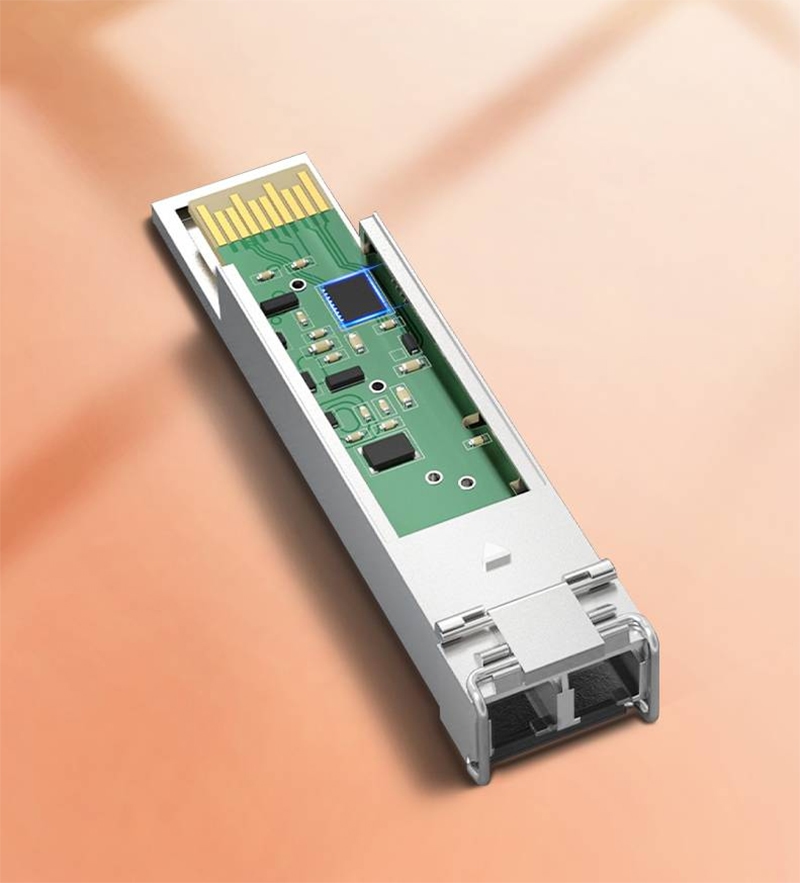
When selecting 1.25G SFP modules, it is important to better understand the technical specifications. The wavelength specification is important because it affects both compatibility with the fiber and performance. For single-mode modules, the wavelengths are typically 1310nm or 1550nm. In multimode modules, the wavelength is usually 850nm.
By understanding the different types of wavelength, you can save time and money by not mistakenly deploying modules based on incorrect specifications. Trying to plug modules into fiber they won’t work for creates deployment delays.
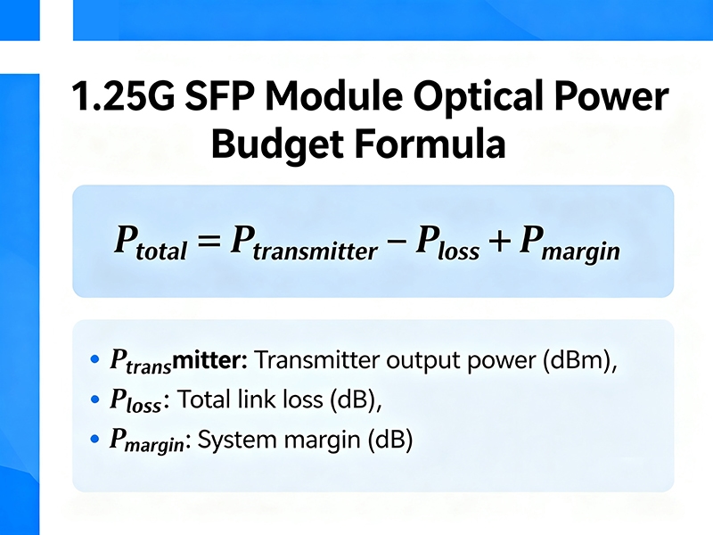
Optical Power Budget Formula:
Link_Budget (dB) = Ptx_min (dBm) – Prx_min (dBm) – Safety_Margin (3dB)
For standard 1.25G modules:
- Transmit Power: -3 to -9.5 dBm
- Receive Sensitivity: -14 dBm
- Available Budget: 11 dB – 3 dB = 8 dB usable
Link Loss Calculation:
Total_Loss = (Fiber_km × 0.35 dB/km) + (Connectors × 0.5 dB) + (Splices × 0.1 dB) + 0.5 dB aging
Transmission distance ratings determine deployment feasibility across a variety of network topologies. Cat 6a transmits at distances of ~100m to meet the specifications for single mode and typically has a maximum range of 550m on multi-mode fiber. Long reach modules are capable of connecting cables at lengths of ~10km on single mode fiber. Furthermore, there are modules, known as Extended Reach, that can exceed 40km of transmission distance to accommodate designs beyond the standard metrics for commercial applications. For comprehensive media comparison analysis: Review our Copper vs Fiber SFP Guide.
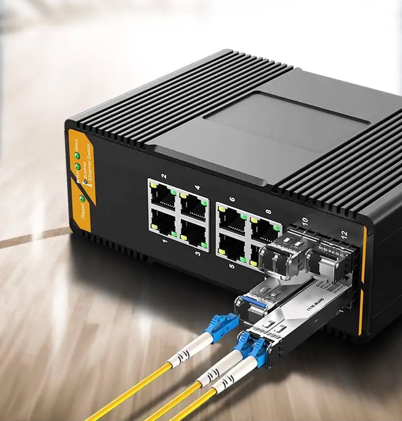
The type of connector will also determine the physical compatibility with existing fiber terminations. LC connectors are commonly seen in enterprise environments primarily due to their small footprint and reliable transmission. SC is often seen in telecommunications termination designs, and the ST connector is used for legacy applications that require threaded connections to provide substantial physical stability.
Verifying the support of the SFP GE T device may require diagnosing and understanding the hardware support. Every vendor provides a checker, known as the Hardware Compatibility List (HCL), for their switches to outline the official hardware support to consider the validity of your deployment. If you are verifying parts against anything other than their official documentation, you could incur 85% return costs all for peace of mind that the module could exist at that compatibility. For technical insights on hardware specifications: Explore our SFP Pinout Technical Guide.
Module Selection Decision Matrix:
| Application | Distance | Fiber Type | Wavelength | Temperature | Module Type |
| Campus LAN | <2km | SM G.652 | 1310nm | 0-70°C | Standard SX |
| Industrial | <10km | SM G.652 | 1310nm | -40-85°C | Industrial LX |
| Long Haul | >10km | SM G.652 | 1550nm | 0-70°C | Extended LH |
| Multimode | <550m | OM3/OM4 | 850nm | 0-70°C | Multimode SX |
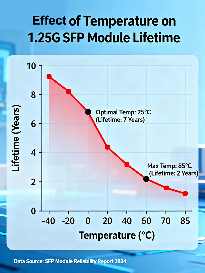
Temperature Impact on Module Life:
| Operating Range | MTBF Hours | Relative Lifespan | Cost Premium |
| 0-70°C | 200,000 | 100% baseline | Standard |
| -10-85°C | 150,000 | 75% baseline | +15% |
| -40-85°C | 100,000 | 50% baseline | +30% |
Vendor certification standards provide assurances for interoperability in a variety of networking environments. MSA-compliant modules ensure baseline functionality with a majority of switching platforms. Coded modules offer patch diagnostics and vendor updates and features. Generic modules do provide 40-60% cost savings but may not offer enhanced monitoring.
For example, the upgrade of the Mayo Clinic network of 1800 ports provided a rationale for systematic selection methodology. The network covered a campus of 15km, which required long-reach modules at 1550nm and yielded a savings of 25% compared to fiber optic replacement while providing a latency of less than 1 ms for medical-centric applications.
 Best Practices for Installing 1.25G SFP Modules
 Best Practices for Installing 1.25G SFP Modules
Physical installation begins with proper electrostatic discharge protection to prevent damage to the module. Just before inserting the module, remove the dust caps from both the module and the switchport. Position the module carefully with respect to the opening of the cage so that it is clearly oriented to seat properly in the keying mechanism incorporated into the module housing. Gentle downward pressure will fully seat the module into the switchport when pressure is applied until the retention mechanism snaps into place.
Installation Checklist:
- ESD equipment verified
- Module compatibility confirmed via HCL
- Fiber cleaning material prepared
- Switch configuration backed up
- Area environmental conditions recorded
- Optical power meter is calibrated
- Cable continuity tested
A correct and clean installation of a new fiber module requires careful attention. Using isopropanol alcohol and lint-free wipes, clean the ends of the fiber prior to connection input. Insert the fiber connectors firmly until it clicks as a way to indicate that it is seated into the module receptacle. Verify the connector polarity is as required by the link in order to transmit TX to receive RX at the remote end.
Configuring a 1.25G SFP typically only involves configuring the switch side with minimal settings for basic operation. Access the switch management interface and navigate to the specific port which houses the module. If the auto-negotiation process is unable to establish proper link speeds, configure the interface speed to 1000 Mbps.
Multi-Vendor Configuration Examples:
HPE Aruba 2930F:
interface 1/1/1
speed-duplex 1000-full
no shutdown
admin-state enable
Juniper EX4300:
set interfaces ge-0/0/1 speed 1g
set interfaces ge-0/0/1 link-mode full-duplex
delete interfaces ge-0/0/1 disable
Dell N3248TE:
interface ethernet 1/1/1
speed 1000
duplex full
no shutdown
In specific deployment situations, duplex settings will need explicit configuration. Full-duplex provides optimal performance since both transmission and reception occur simultaneously. Half-duplex only applies to situations involving legacy device interconnections and rarely, if ever, will apply to fiber connections. Auto-negotiation should automatically negotiate speed and duplex parameters between compatible devices.
Auto-negotiation should only be disabled when there are specific compatibility issues requiring a manual static configuration. The command(s) mentioned above for initiating the verification only confirm the successful SFP GE T configuration and functionality, as well as a baseline configuration for speed and duplex settings. Next, the appropriate show interface commands should be run to verify that the link is up and that the speed and duplex settings confirm that configuration requirements were met.
Verification Commands by Vendor:
| Platform | Interface Status | Module Details | Optical Power |
| HPE Aruba | show interface 1/1/1 | show system sfp | show interface transceiver |
| Juniper | show interfaces ge-0/0/1 | show chassis hardware | show interfaces diagnostics |
| Dell | show interface ethernet 1/1/1 | show system sfp-plus | show environment temp |
The link status indicators give real-time feedback on the success of the link. A green LED status generally indicates that the module has been recognized and fiber connections are active. An amber status may signify configuration mismatches or that a physical connection issue is present and should be addressed as soon as possible. Optical power measurements determine that the signal strength is operating within acceptable limits.
Generally, most switches provide basic information about optical power levels either through show commands to assist with determining fiber connector issues early in your deployment.
Troubleshooting Common 1.25G SFP Module Issues and How to Fix Them
Intermittent link drops are a common issue in manufacturing environments and troubleshooting 1.25G SFPs for multiple signals to maintain continuous operations. Recently, a large automotive plant began experiencing random disconnects every 2-3 hours across multiple fiber connections all at the same time. The diagnostic commands indicated that the modules were experiencing temperature variations that exceeded specifications during peak production times. Once cooling was enhanced and the equipment was moved, thermal-induced failures were eliminated.
The categories of failures are as follows:
Link Flapping Problems – 35% of failures:
- Temperature fluctuations exceeding 5°C
- Loose fiber connections
- Optical power levels near marginal
- Sources of EMI interference
Module Recognition Failures – 25% of failures:
- Vendor coding issues
- Firmware versioning
- Corruption of EEPROM data
- Inadequate power supply
Distance/Power – 20% of failures:
- Transmission distance
- Fiber insertion losses
- Dirty or damaged connectors
- Wavelength mismatch
Environmental Effects – 15% of failures:
- Vibrations such as >2G acceleration
- Corrosion from humidity such as >80% RH
- Dust
- Power quality issues
SFP GE T errors are frequently seen due to compatibility issues between the module and the switching platform. Coding errors common to educational facilities occur when third-party modules are used. Using the commands to examine the module inventory will indicate the detailed part numbers along with certification status of modules. Typically, a firmware update or replacing the module with an MSA-compliant module will resolve some of these failures. When troubleshooting module recognition issues: Access our SFP Detection Troubleshooting Guide.
Distance-related issues develop when fiber runs approach or exceed the transmission distance. Hospitals or facilities that are doing business across a large campus frequently experience this condition. Symptoms include loss of packets or performance degradation. Optical monitoring will indicate loss of optical power due to fiber signaling.
Calculating the optical budget will help to determine if connectivity issues are fiber quality-based or distance-based.
Reference Commands for Diagnostics:
Power Levels Analysis:
- -3 dBm: The signal is too strong (put in an attenuator).
- -3 to -12 dBm: The power level is considered good.
- -12 to -14 dBm: Acceptable, but watch the trending.
- -14 to -16 dBm: Marginal, begin looking for losses.
- <-16 dBm: Link has reached its failure point.
Cable infrastructure failures can create persistent connectivity issues if a systematic process for isolating each segment of the cabling is not followed. In warehouse situations, there is frequent traffic over fiber runs that have been buried under a cement slab, which can cause intermittent link failures. The time-domain reflectometer (TDR) tests can help identify where the failure has occurred in the fiber span. A visual fault locator is another tool that can greatly assist in identifying where the physical damage is and can sometimes help track the fiber path.
The diagnostic commands will provide great insight into the health of the module, in addition to parameters related to performance. The commands regarding the interface counters will display if CRC errors are occurring, if there are input drops, as well as other anomalies related to the link status. There is also an environmental monitoring feature that will display the thermal readings and let you know if there is a cooling problem that could affect the stability of the module.
Troubleshooting, or problem-solving, should be a systematic process:
- Inspect the physical layer (connectors, cables, seating, and tightness)
- Measure power at the optical level (Tx and Rx levels)
- Assess environmental conditions impacting the link (temperature, vibration)
- Verify switch application settings (speed, duplexing, VLAN assignment)
- Confirm module compatibility (HCL, firmware)
- Analyze interface error counters (CRC, drops, and collisions)
- Test known-good replacements.
Regulatory compliance requires banking networks to have the same firmware version on all of the networking components. When firmware is not the same, this can produce unpredictable behaviors and can sometimes exacerbate other issues with the technology itself. To remedy the issues, either the firmware on the switch should be upgraded to the same version as the modules, or the modules should be replaced with the correct version of firmware that is compatible with the switch.
The pattern of hardware failures does follow a predictable trajectory before the complete failure of the module. As hardware, an optical transponder’s laser will eventually degrade to the point where it is simply not functional, which can typically be monitored through a slow but gradual reduction of the optical power level over a period of months. Consistent monitoring will help identify drops in optical power levels before a complete linkage failure occurs, when your business can least afford the outage.
In challenging deployment environments, monitoring new environmental conditions can be the difference between thermal-induced failure of the module. In poorly air-conditioned data centers, the failure percentages increased in the summer months when the advice from the OEM indicated that the power should not exceed sixty degrees C. The other recommendation was that if temperatures in the data center continued to reach around sixty degrees, the infrastructure should provide temperature monitoring with automated alerts to protect the sensitive components.
The fluctuation in power supplies can affect the stability of the module in many industrial settings that have variable loads and power supplies. A processing facility that has several variable loads and uses heavy machinery can have significant voltage changes that can affect the proper function of the switch. Continuity of power via uninterruptible power supply systems should be sufficient for running normal power, while isolating and protecting sensitive components from additional electrical problems that will damage the optical modules.
 Why Proactive Maintenance Extends the Life and Reliability of 1.25G SFP Modules
 Why Proactive Maintenance Extends the Life and Reliability of 1.25G SFP Modules
The SFP 1G maintenance schedule plays a major role in operational longevity in enterprise settings; therefore, it is extremely important to manage and protect your capital investment the right way. For preventative maintenance purposes, monitoring optical power every 30 days will identify any gradual degradation of the laser projector, prior to imminent laser failure. Telecom carriers have established a systematic procedure for monitoring power levels; in each case, this extends the functional life of the SFP modules by 40%-60% longer than an as-is reactive maintenance approach. In some cases, this opens up parameters for predicting SFP replacement schedules, awaiting laser signal degradation by monitoring power levels.
Predictive Maintenance Parameters:
- A 1 dB decline in power levels indicates replacement being recommended within a 6-month period.
- A 2 dB decline in power levels indicates replacement being recommended within a 3-month period.
- A 3 dB decline in power levels requires immediate replacement.
- Temperature >85 degrees Celsius requires an emergency shutdown of SFP modules due to thermal failure and acute damage to the SFP module’s internal electrical components.
Connector cleaning procedures will prevent a buildup of contaminants from the environment into the connector from degrading signal quality at various points in time. Monthly pre-emptive cleaning of BNC connectors will remove dust, oils, and microscopic particulate debris that accumulate, inducing excess insertion losses over time. Even in the sterile world of the pharmaceutical industry, airborne particles still accumulate, requiring a regular rigorous cleaning schedule. Clean connectors will ensure signal continuity remains intact, avoiding sudden signal collapse and negating significant costs associated with degrading signal power.
Performance updates (firmware) are required and should be gauged approximately every 3 months (depending on the switching software release schedule) to maintain compatibility with switch components, importantly, security patches on the switch. Quarterly reboots to maintain module firmware will keep the SFP status reporting functions aligned with the protocol standards in complex network environments. Data/financial institutions have mandated coherent firmware versioning for SFPs as a requirement for compliance audits and to address security vulnerabilities from switch firmware failures.
Firmware releases typically contain performance improvements for the 1.25G functionality of the SFP modules.
Maintenance Programs – cost benefit:
Let’s see what these maintenance practices are costing:
- Program cost = $15/year per module
- Reactive maintenance avoided = $85 per module
Taking yearly savings per module, it would look like:
- Yearly Savings = $70 per module
- Payback period = 2.6 years
- 5 Discounts ~ 2233% ROI over 5 years.
Furthermore, environmental control systems are crucial to SFP operational lifespan—temperature and humidity. Even within data center headquarters, they require ambient temperature control at 22 – 24 degrees Celsius, which extends the operational life of the module by 200%-300% compared to non-temperature-controlled environments. Corrosion of optical components occurs under excessive humidity-based temperature conditions or near other processes within industrial plants that cause thermal expansion and shrinkage in extreme temperature ranges.
Over periods of signal operational life, heat during the summer season reduces sustained thermal expansion in the electrical components of the SFP. Utilizing additional cooling systems can extend the life of a module during the summer months in industrial applications. Lastly, vibration controls—these systems can become important in a manufacturing environment where heavy pieces of machinery are operating through constant mechanical stress upon SFP modules, usually located in nearby rack spaces.
There are reported areas where automotive manufacturing plants utilizing anti-vibration mount systems have reduced SFP module failures by 85%, compared to modules mounted in a standard racking system. Having units that are shock-resistant protects optical lens components from being damaged through everyday activity, such as the service technician performing maintenance on other standard optical components within the surrounding environment. Possible areas are facilities located in the direct transportation approach to and from airports, where vibration impacts are mitigated from landing aircraft.
Lastly, power quality—monitoring electrical malfunctions could identify power issues before eventual module failure occurs due to uncontrollable factory issues. Power switches often have voltage regulators and surge suppressors under stress within manufacturing environments containing arc furnaces. A steelmaking plant would identify the high level of electrical noise coming from the power source itself, particularly recurring electrical noise from arc furnaces.
They would replace switching devices often due to poor power quality delivery. Good, clean power will not only prolong the operational life of modules, but it will also ensure their primary functions optimally operate the laser, creating higher levels of signal integrity. If power delivery is cleaned up, the modules will be less likely to experience sudden failure signal collapse.
Environmental Impact on MTBF:
| Factor | Optimal Range | MTBF Improvement | Implementation Cost |
| Temperature | 20-25°C | Baseline | HVAC systems |
| Humidity | 45-55% RH | +20% lifespan | Dehumidification |
| Vibration | <0.5G | +15% lifespan | Isolation mounts |
| Power Quality | ±2% voltage | +25% lifespan | UPS/conditioning |
Documentation systems keep a record of maintenance histories and performance trends from widespread module deployments in the field. Retail chains that deploy thousands of modules utilize automated monitoring systems that can log system temperature and voltage or power levels, as well as error rates in real time. This telemetry data allows for predictive analysis that will forecast replacement of the item weeks before any failure event actually occurs.
The storage conditions of spare modules will have an effect on shelf life and “as-new” performance of the products. A climate-controlled storage environment of 15-25°C with 45-75% relative humidity will allow for long-term storage and the ability to maintain factory specifications. Emergency response agencies maintain spare modules at strategic locations to allow for the rapid deployment of the item during disaster recovery operations. Storing spare modules properly in the field will allow an agency to operate the module reliably as soon as the spare module is required and put into service immediately when needed during a critical network outage.
Conclusion
To deploy your strategic 1.25G SFP, an understanding of your business scenario, technical specifications, and compatibility is essential. The maintenance of effective compatibility checks, component selection, and flexible distance requirements are critical to deploying the proper module. Having to consider the distance limitations and any relevant budget constraints can dictate the module you select. Again, performing controlled verification processes that ensure vendor compatibility is an absolute must.
Lastly, the physical installation requires an understanding of keeping the connectors clean and inserted correctly for reliable connectivity. If the deployment reaches into the realm of Tier 1 SFPs and the associated problem-solving, systematic troubleshooting methods identify the root causes using diagnostic commands or environmental watchlist-based menu commands. Keeping the SFP GE T schedules and deploying best practice maintenance schedules for deploying the SFPs extends the operational life, while preventative measures during proactive maintenance scheduling of the SFPs can remove the risk of unanticipated failure.
Depending on the SFP type, proper environmental controls prevent the damage caused by temperature fluctuations or physical mechanical damage. Organizations that are managing legacy infrastructure will benefit tremendously by implementing these strategies, as they are proven best practices. When properly timed or utilized, selecting under purpose and ensuring maintenance schedules become part of the routine, the value and return on networking investments become stretched and elongated.
Network administrators should be applying these practices systematically in all scenarios of deployment to optimize the SFP deployment.